|
|
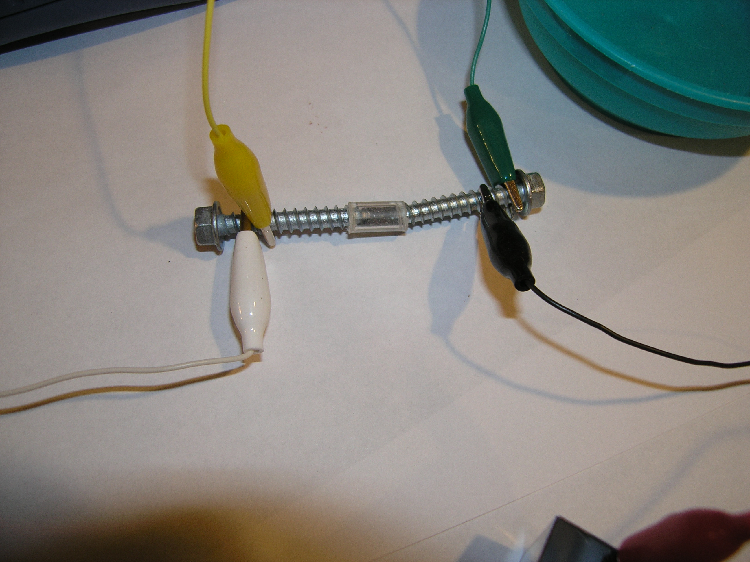
Some of my other projectsMight as well put them here... CohererThe first device to detect radio waves for practical use was a "coherer". Developed in the late 1800's, it simply consisted of a tube with two electrodes separated by a loose pile of iron filings. In its resting state, the coherer provided high resistance to current on the two electrodes. However, when it was hit with a strong radio wave the resistance drops to a low value. If the sender and reciever then agreed on a rate of transmission, you've got all you need to transmit messages through the air. At the time, the radio wave was supplied by a spark gap transmitter. I'd read about these things long ago, and the part I remember most was what happened after the device "cohered". To reset it, you'd have to physically jostle the coherer. This led to a lot of really interesting inventions to automatically kick the coherer after it activated. I recently ran across an excellent web page which described how easy it is to make your own coherer: http://home.earthlink.net/~lenyr/coherer.htm Of course, I had to try one myself. It took about a half-hour, and worked first time out of the box. Here's a picture:
I cut a section of a clear Bic pen for my "glass tube", and got my pinch of filings by putting an old nail in a vice and working it over with a file. For my spark gap transmitter, I used the igniter from my rusty and broken gas barbeque. I have an idea to do an even more twisted and elaborate project based on this. We'll see if I can find the time. Here's a YouTube video of it working:
Simple Laser SpirographI think my wife now regrets giving me a green laser pointer for Christmas a couple of years ago. It's a great little gadget - and I'm constantly shooting it around the house. I thought it would be fun to try to recreate a laser light show, so I put together a little spirograph machine. Here's a video of it:
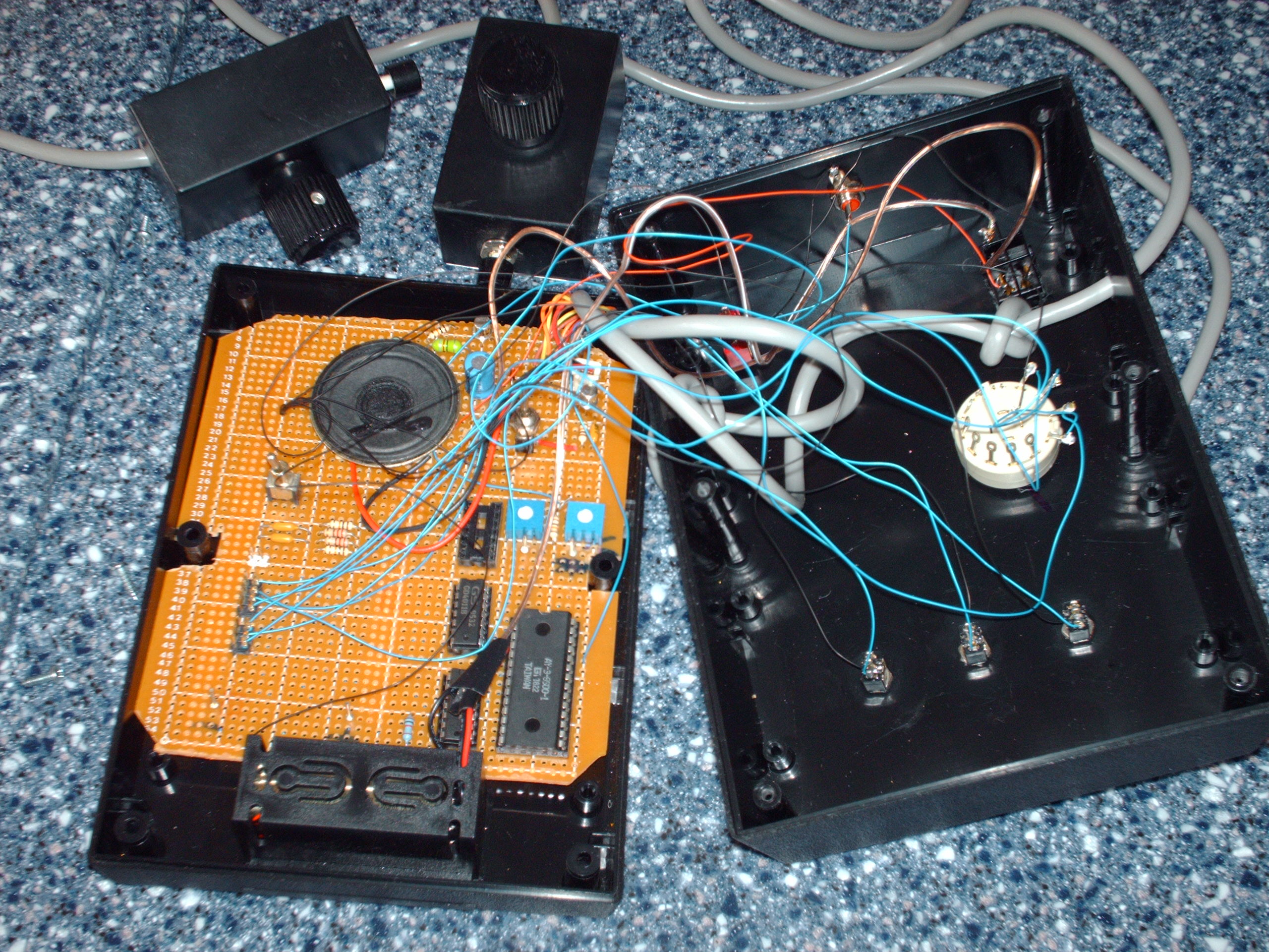
It looks a lot better in person (the frame rate of the video camera warps the picture somewhat). One thing I didn't mention in the video clip is that the mirrors have to be slightly off-perpendicular to the motor shaft. It turns out this is very easy to do (and in fact, it would be a bit harder to get them perfectly perpendicular). I attached the mirrors using double-sided foam tape, and it was irregular enough to give me all the offset I needed. I doubt I'll ever get around to it, but the next steps would be to add a mount for the laser and an additional mirror attached to a speaker cone. Oh, and of course, then turn off the lights and play "Dark Side of the Moon". Pong gameA few years ago I picked up an AY-3-8500 "pong-on-a-chip" device on eBay. It made for a quick weekend project. With a few simple components, I was able to show the kids what a real video game was like. Will was almost impressed. Here are some pictures:
And here is a video of it in action:
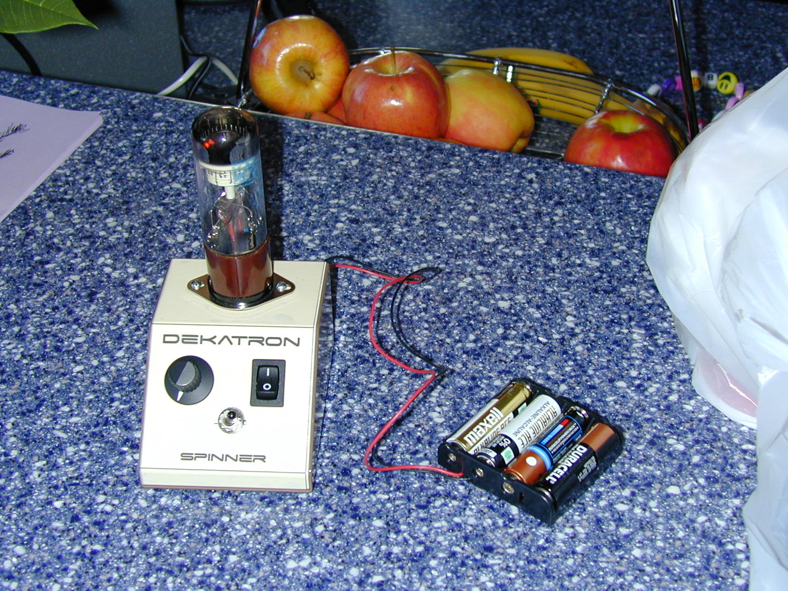
Dekatron spinner #2
The first dekatron spinner I built was based on plans at Mike's Electric Stuff page. It spun pretty fast, at a fixed rate based on the 60Hz line frequency. I donated that spinner to Transmeta when I left in 2002. I recently decided to build another spinner - but this time with variable speed. For the power supply I'm using a 5V florescent tube driver, which allows me to even run the thing off of batteries. Besides the florescent driver, the spinner is quite simple inside: a 555 timer for the pulses, feeding into a 4017 to drive the MPSA42's that ground the common cathodes, guide 1s and guide 2s in sequence. I route the control signals for guides 1 and 2 through a switch to add the ability to reverse directions. The unloaded output of the florescent driver is about 700 volts, which I drop through 4 1M ohm resisters before powering the dekatron's anode. I'm pleased with the way the enclosure worked out. I printed on Avery transparent full-page label stock and then overlaid the enclosure top. The big holes were cut with a nibbler. The other holes were made with a hand drill (and the bit walked when doing the direction switch :-( - got to get a drill press one of these days). Overall, it was a weekend afternoon project. I have enough parts to do another one, so I'm going to give this one away in my work group's holiday gift exchange. Crystal Radio
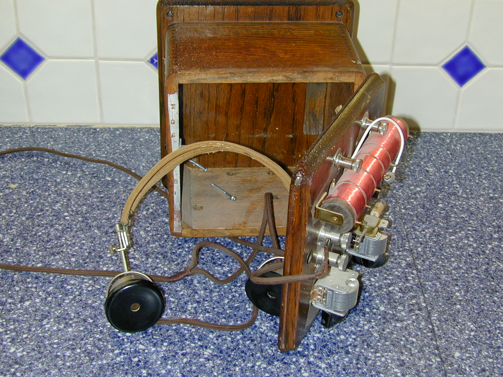
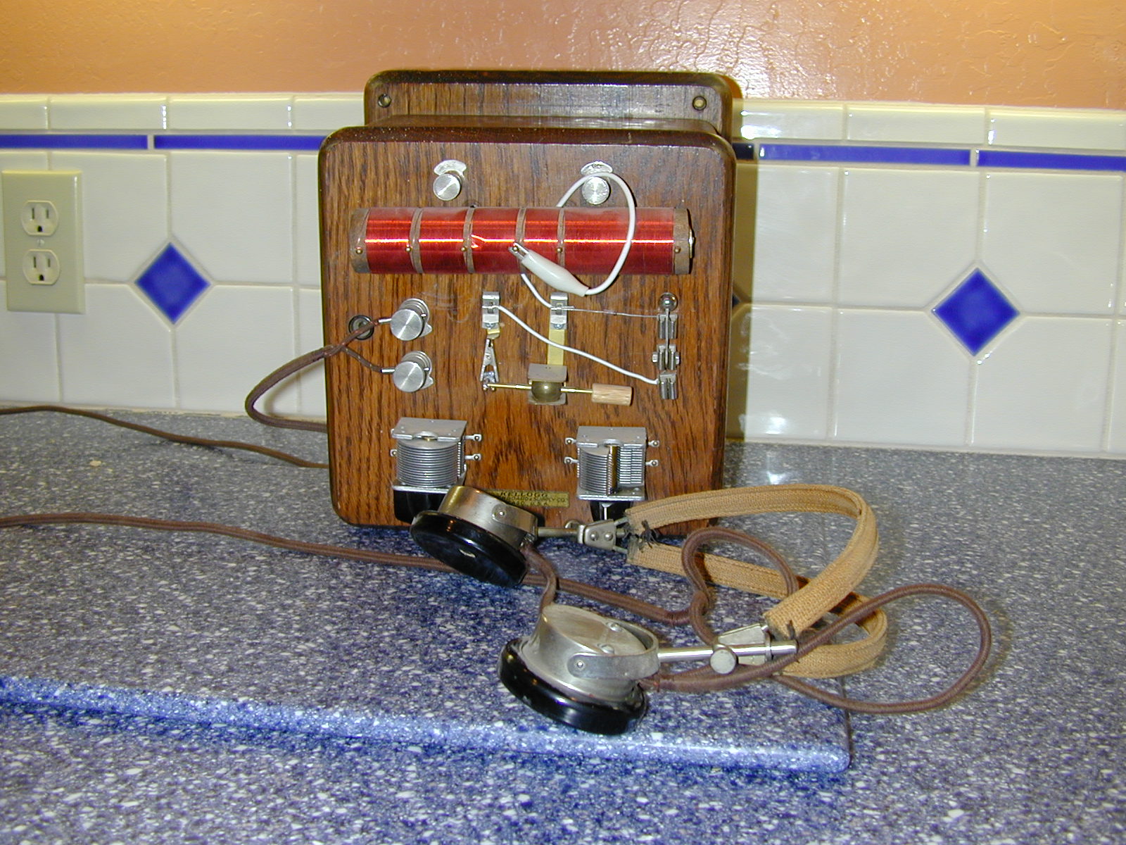
I don't think it's possible to qualify as a nerd without having built a crystal radio. I did build a few as a kid - but only from a kit and I never really knew what I was doing. Still don't, but am a bit closer. Anyway, this project started when I was surfing eBay a few years ago and ran across a listing for an old radio crystal in a little round tin. It's what a kid in the 30's would have sent away for mail order if he wanted to build a radio. It contained a "guaranteed galenium crystal". Couldn't pass up trying to replay that pre-transistor experience, so I bid high and won the auction. Next step was finding a book or instructions that would have been used by that 1930's kid. What I came up with was the "Boy's First Book of Radio and Electronics". It was actually a bit later than the 30's, but was just what I was looking for. While searching the web for crystal radio stuff, I found The Xtal Society - you need go no further than this, it's a fantastic resource. There I was able to purchase a couple of air-variable capacitors, and though another contact some excellent 1918 headphones. I built my radio on the outside lid of an old telephone ringer box. The idea was to have the radio on the outside of the box, and store the headphones inside. It worked out well - radio mounted on the wall, and held the headphones. For the hardware, I used some parts salvaged from an old Wheatstone bridge. The knife switch selected between by eBay crystal and a modern diode. As it turned out, the modern diode was only marginally better than the crystal. I wound the coil around a dowel, spinning it with a cordless drill. The final part of the project was to string an antenna. I ran a single copper wire in the inside of my attic. I'm not especially happy with that - at some point I think I'll do a longer one wrapped around the eaves of my roof. The radio works pretty well, though I do get a bit swamped by a nearby San Francisco station. Or at least the radio did work well. One of the kids mushed the blades of one of the air-variable capacitors together, shorting it out, and I had to unmount the radio from the wall during a recent kitchen remodel. One of these days I'll order a new one from the Xtal society and get it going again - perhaps with that improved antenna. Monica's Dekadog Kitchen Timer
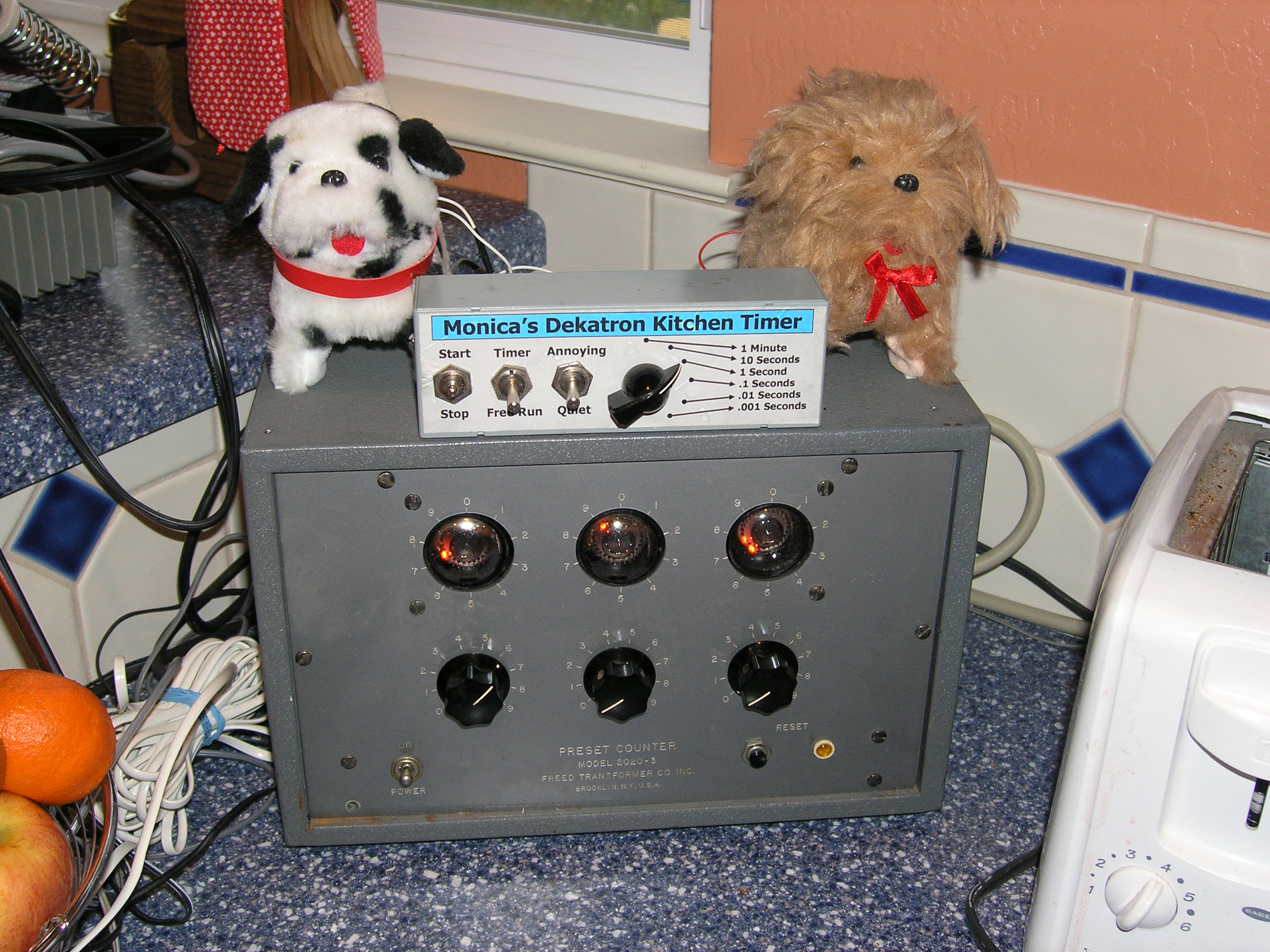
While questing to build a Nixie tube clock, I ran across references to Dekatron tubes and thought they looked pretty cool. I added "Dekatron" to my Ebay standard searches, and in the summer of 1999 (or 2000) a preset counter showed up for auction. I had to have it, and did (for about $50). A preset counter is a piece of industrial equipment that counts electronic pulses. When the count equals the number preset via front-panel knobs, a relay is thrown. These were used for things like controlling the number of turns of wire that went on a spool - really anything on the factory floor that needed counting. This particular counter used Dekatron tubes as the counter elements. If you hit them with the right wave patterns, it will make the neon glow bounce from one pin to the next. It's set up to normally bounce three pins for each input signal. With 30 pins, that allows you to count to 10. It then uses old vacuum tube triodes to generate the carry into the next tube. With 3 tubes, it can count from 0 to 999. When the counter arrived, it didn't take long to see that it worked perfectly. I found that I needed to send it an AC wave to count (and used my old Heathkit breadboard for the signal). The real issue, after I played with it for awhile, was figuring out what to do with it. My wife had been teasing me a bit about my toys, and had hinted that the exceedingly important work that I was doing had no useful point. Heresy! So, to prove her wrong, I decided to convert the preset counter into a kitchen timer. It's pretty simple, really. I built a little box with a 1 Mhz crystal and a series of dividers to give me time bases of 1 minute, 10 seconds, 1 second, .1 seconds, .01 seconds and .001 seconds (the later important - you never know when you need to cook that toast for an additional .034 seconds). I fed the basic square wave signals into a Max 232 device to give me a -10 to +10 voltage swing and ran that into the preset counter's input. For the alarm device, I originally planned on getting one of those toy monkeys with cymbals and drums. However, at the toy store I found a couple of little irritating barking dogs that resembled our irritating real dogs (a golden and black & white Aussie). I had to go with those. So, for controls it has three toggle switches: start/stop (controls the pulses), timer/freerun (to give me a mode where I can just watch the lights cycles) and quiet/annoying (to control the alarm). To encourage Monica to actually use it, I also went through the house and collected all of the existing kitchen timers, and threw them away. Fortunately, Monica is a very good sport and actually uses the silly thing. Here's a little video of it running
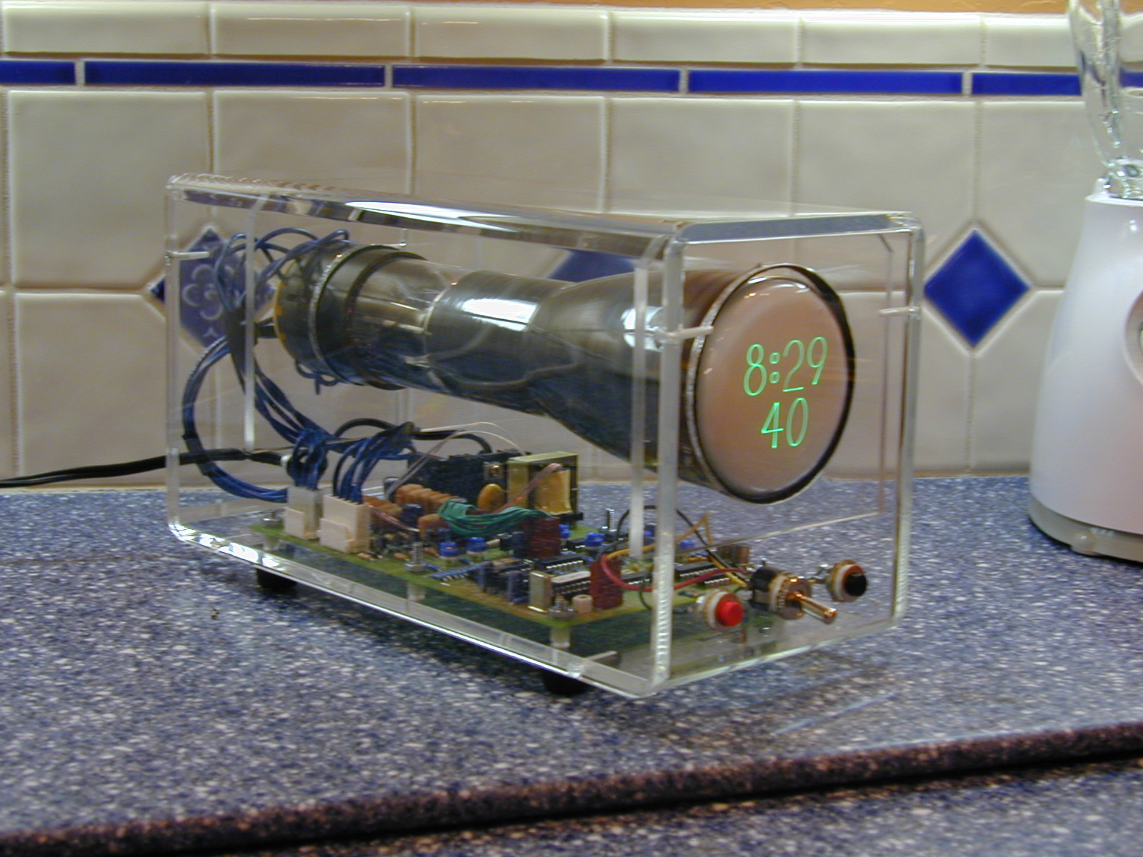
Scope Clock
The scope clock is a very cool kit project designed by David Forbes at http://www.cathodecorner.com. I heard about it from a posting David made to the Greenkeys teletype enthusiast mailing list, and ordered one of the first kits. However, it took me a couple of years to get around to putting it together. Nixie Tube Clock #1 and Dekatron spinner
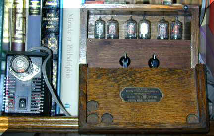
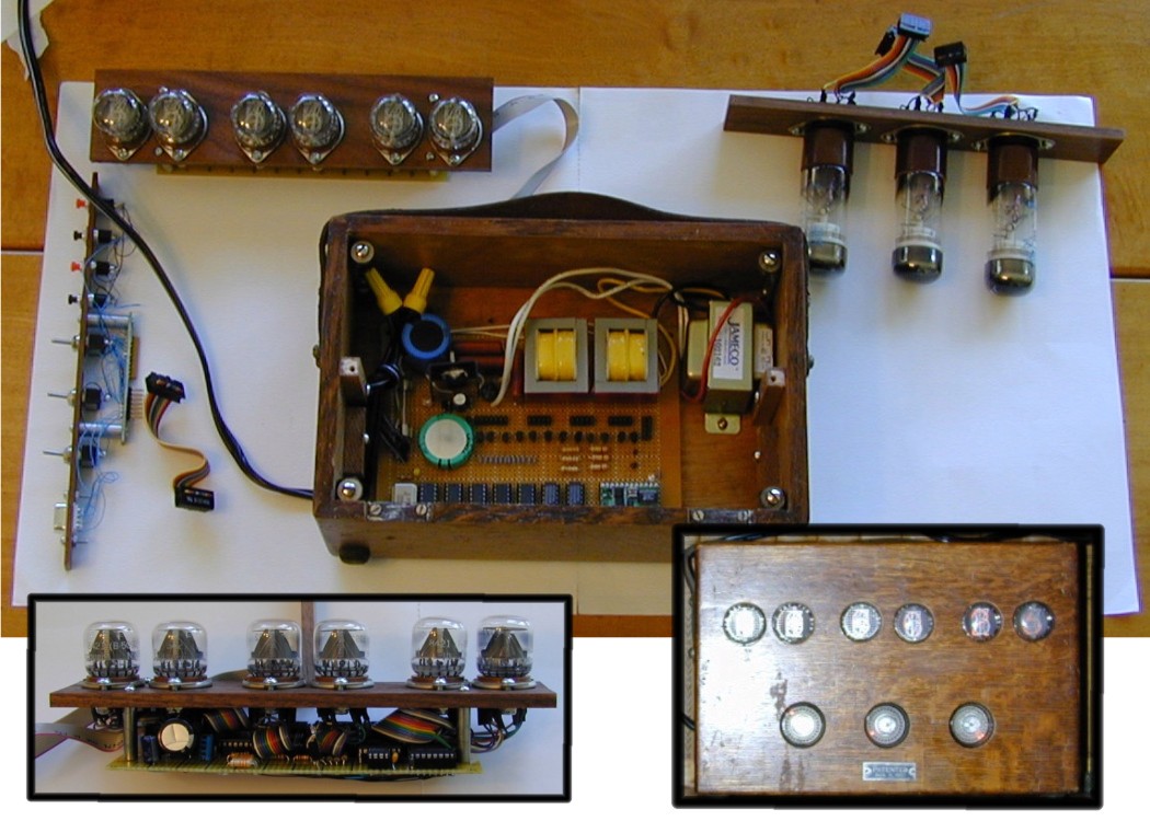
This is the first Nixie tube clock I built. It's done inside an old ammeter case, and looks a lot better in person than in the picture. I used a couple of rotary switches to set the time. The left one selects the digit, and the right sets the value. When the left-most switch is at the 12:00 position, it puts the clock into run mode. I thought it would be easier this way, but in retrospect it really isn't. The Nixies are powered by running a couple of transformers back to back with secondaries connected to give me ~165 volts. A bit low, but it was enough to light the tubes. One of these days I hope to get around to replacing that with a more modern switching supply (like I used in my 2nd clock, below). I originally designed the clock to take its clock source from the 60 hz line input, but my circuit design was faulty. I ended up just stuffing in a clock chip with a 1 second output pulse. Inelegant, but it works. To the left of the clock is a dekatron spinner I built, using the circuit from Mike's Electric Stuff page. Combo Nixie Tube/Dekatron Clock
This is a collage of photos of my combo Nixie tube/Dekatron clock. I keep this one at my office at work, and am quite pleased with it. The six nixies along the top give the time, and the three dekatrons on the bottom spin at 100, 10 and 1 HZ, reversing directions every 30 seconds. I used a switching power supply for the Nixies, and voltage multipliers for the dekatron. The time base is a 1 MHZ crystal, with dividers to give 100 HZ. Everything is controlled by a Basic Stamp IIx microcontroller (which was just barely fast enough). Here's a quick (and fuzzy) video of it running:
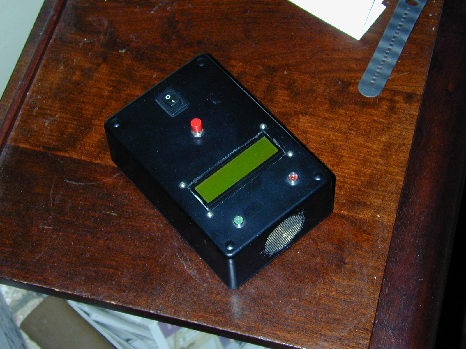
Ultrasonic Rangefinder
Pretty simple, but slick - I built a ultrasonic rangefinder using the guts of a Polaroid camera. All of the hard work is done by the ultrasonic rangefinder module. All I had to do was arrange for the proper power supply, connect it to a microcontroller to time how long it took the echo to come back, convert time to distance and display it on a LCD display. Cosmac Elf
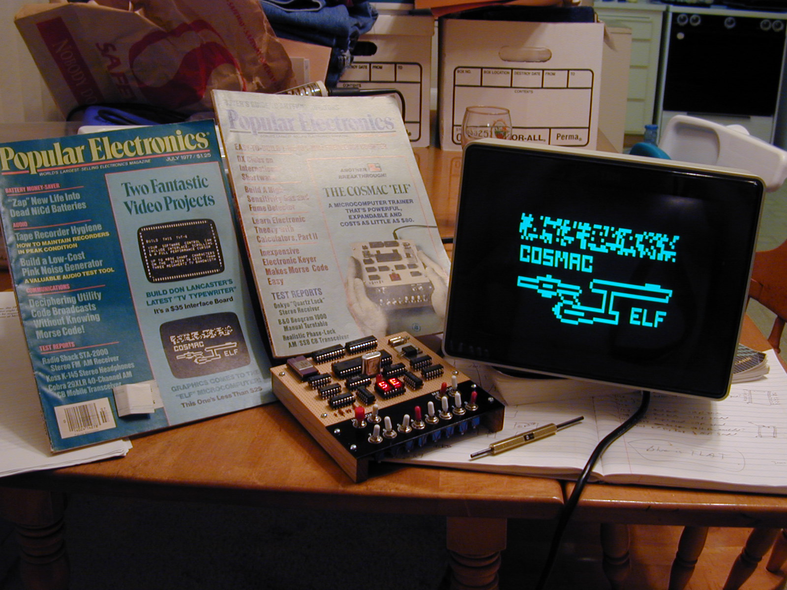
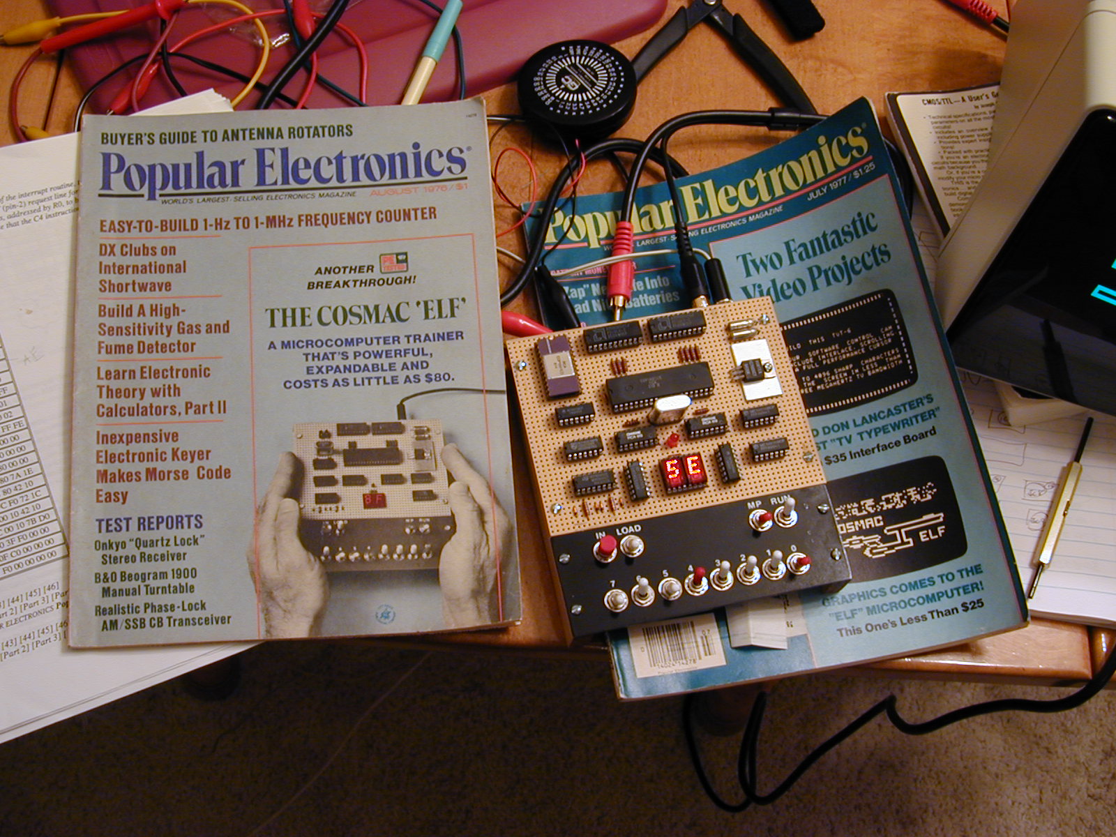
Here's my Elf, with the video enhancement displaying the famous Star Trek screen (note the lower screenshot on the leftmost Popular Electronics magazine).
A closer-look at the computer. You have to enter programs by flipping toggle switches. I'll have to confess that it gets old fast. PDP-8 clone
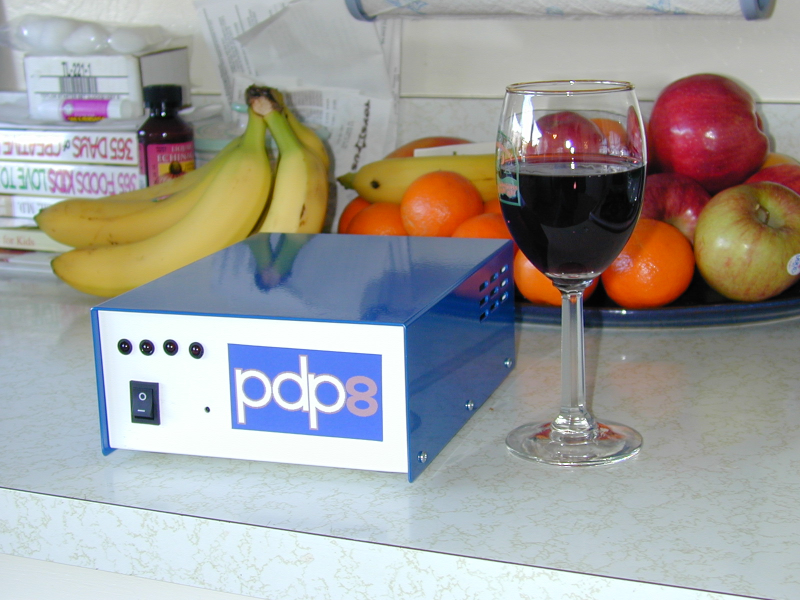
This was a fun project - a PDP-8 clone built using the Intersil 6120 "PDP-8 on a chip" device. The computer was designed by Bob Armstrong, at http://www.sparetimegizmos.com. He posted about it to a computer collector mailing list and a bunch of us expressed interest. Bob had board made and programmable devices programmed and we all went to town. I customized mine a bit by making it battery powered. It uses a sealed lead/acid battery, and can run for five or six hours. Note that after this above picture was taken, I straightened out the row of LEDs (and vowed to use a drill press the next time I need to do a straight line of holes). The little computer works great. I talk to is using Kermit 95, and have had a great time playing the original adventure and experimenting with FOCAL-69. It runs images of the original DEC PDP-8 software. For more info, check out Bob's 6120 page: http://www.sparetimegizmos.com/Hardware/SBC6120-2.htm. 512 Kbyte RAM disk for TRS-80 Model 1My first big electronics project, this as a 512 Kbyte RAM disk for my TRS-80 Model 1. It's pretty simple now, though at the time I thought it complex. It's just a bank of 32Kx8 SRAMS with some latches and addressing glue. A cool feature are the hex displays I added to show which 256-byte sector is currently being addressed. I highly recommend blinky lights for any electronic project. The board's memory can only be addressed in 256-byte chunks, relying on the Z80's INIR and OUTIR instructions. I also wrote a RAM disk driver, based on some existing code. It works great - and provided an astonishing speedup to my old Model 1. Silly EEPROM programmer
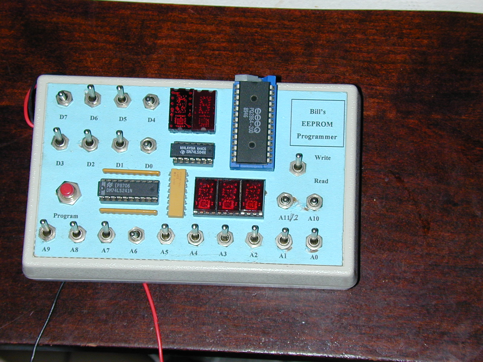
This is a completely silly and useless project, though I was pleased with the way it looked. For a long time I wanted to build an EPROM programmer, as a prelude to building a Z80 computer. Being ignorant of even basic electronics, though, I never could understand the schematics of hobbyist programmers to the point that I could build my own. When EEPROMs came along, though, I figured I could handle that - so build built this simple programmer. Note that you have to toggle in every address and data value. Completely unusable. Model 20 Teletype
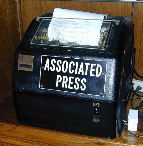
I grew up in a newspaper office, to the sound of old mechanical teletype machines. A few years ago, I decided I needed to hear that sound again and eventually tracked down a Teletype Model 20 - just like we used to have at the newspaper. After building a rs232 to 60ma loop current converter (actually 2 - one of my design which later failed, and a good one designed by Gil Smith) I wrote a control program in Perl. I have a website devoted to that project: http://www.buzbee.net/heavymetal Here's a video of the machine running.
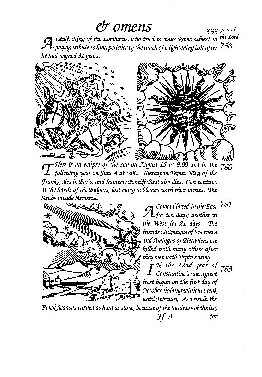
Translation of leaf from 1557 Latin book
Back when I had way too much free time on my hands, I got interested in old printing. I began collecting very old books (mostly from the early 1500s). While visiting a book dealer in San Jose in 1992, he handed me a stack of individual leaves to flip through. I ended up buying three or four - mostly incunabula (pre 1500), and a leaf from Shakespeare's 2nd folio. There was also a single page from an unknown book with really cool woodcuts. One in particular was clearly a comet. I later identified the leaf as being from Lycosthenes' Prodigiorum ac Ostentorum Chronicon - or "Portents and Omens," published in 1557. It was a book listing natural phenomena from the beginning of recorded history. The language was Latin, and because I had a bit of Latin in college I thought it would be fun to try to translate my leaf. That lead to a quite interesting adventure, and really showed me the power of the emerging internet. In the summer of 1992, I posted to the sci.astro newsgroup for help. The words describing the comet gave a date, and I thought it was likely that someone had computed comets back in time. I was hoping for a match. I got great responses (including corrections to my faulty translation) and was referred to several texts. I was excited to discover that my page's comet was actually the AD 761 visit of Halley's comet. Way cool. I constructed my translation using PageMaker and scans of the woodcuts from the original. One thing that impressed me was how well modern font sizes and styles mapped to those used half a millennium ago. No need to change what works. A few years later, I located a complete copy of Prodigiorun ac Ostentorum at an antiquarian book fair in Los 'Angeles. It's the highlight of my collection. TRS-80 Software: Pascal Compiler, Lisp interpreter, Threaded Interpreted Language (FORTH)I taught myself to program using my TRS-80 model 1 in 1980 (and later learned how to do it right...). I had a particular interest in computer languages, and over time wrote several language tools for my Model 1. The most elaborate was my Pascal compiler. It wasn't a complete Pascal (no floating point), but it did include a number of enhancements such as structured constants. The compiler itself was written in that variant of Pascal, and eventually the compiler was able to compile itself. Note that it did this using appx 40K bytes of memory - and that included both the compiler code and heap used. I still have a working TRS-80, but the programs I wrote can be easily run using any of the fantastic TRS-80 simulators available today [TBD - put code/source/simulator links here] Besides the Pascal compiler, I wrote a Lisp interpreter. It was done entirely in assembly language, and I used it to explore garbage collection techniques. It did a fairly simple reference count scheme, with periodic mark and sweep. The main feature was arbitrary precision integer arithmetic. I got a kick out of generating large factorials. It could do appx. 2000! before it ran out of memory. I also wrote a Forth-like language based on an old Byte magazine book "Threaded Interpretive Languages". Big fun, and I still have a fascination for Forth-like languages. Model Ship
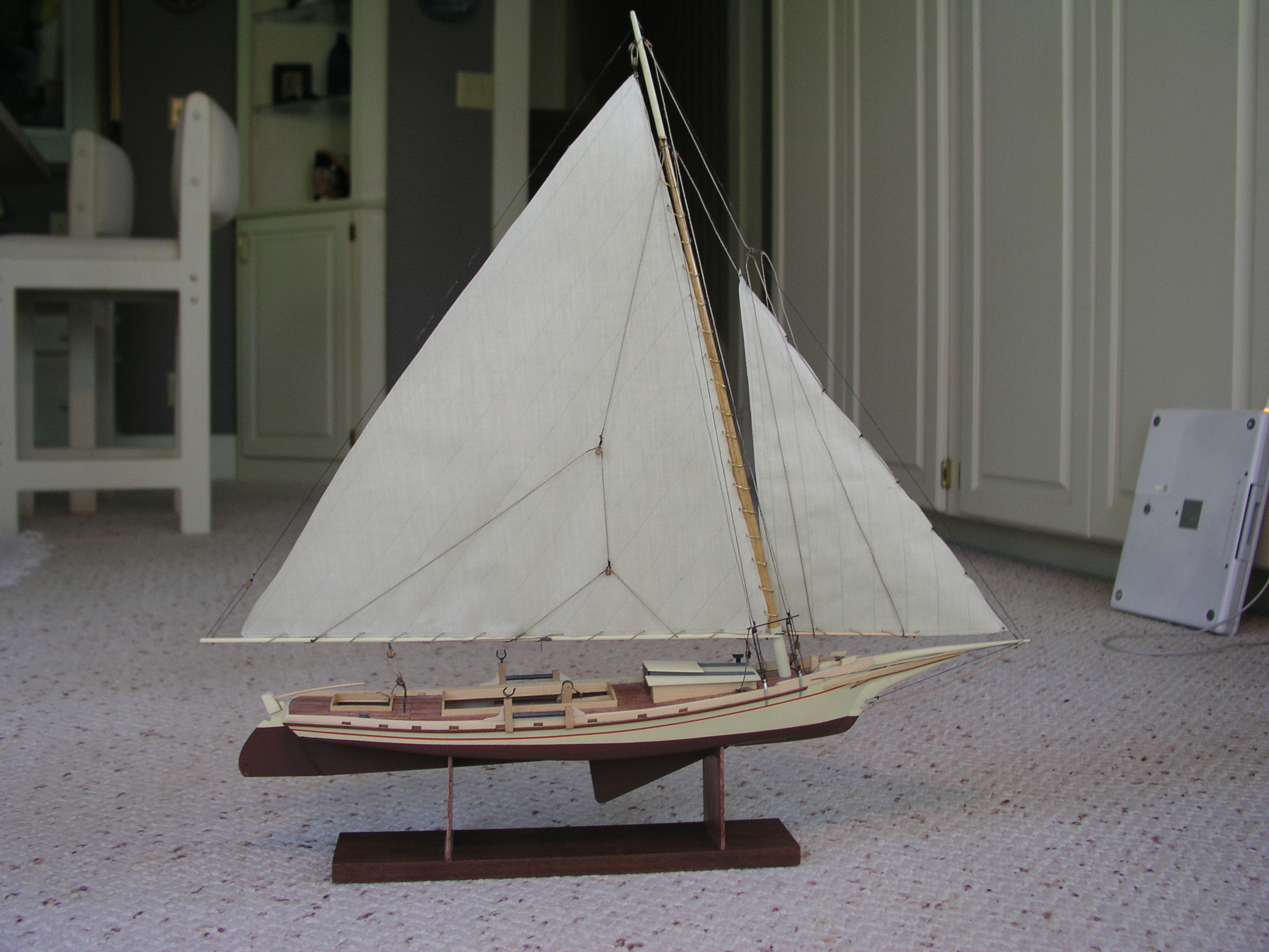
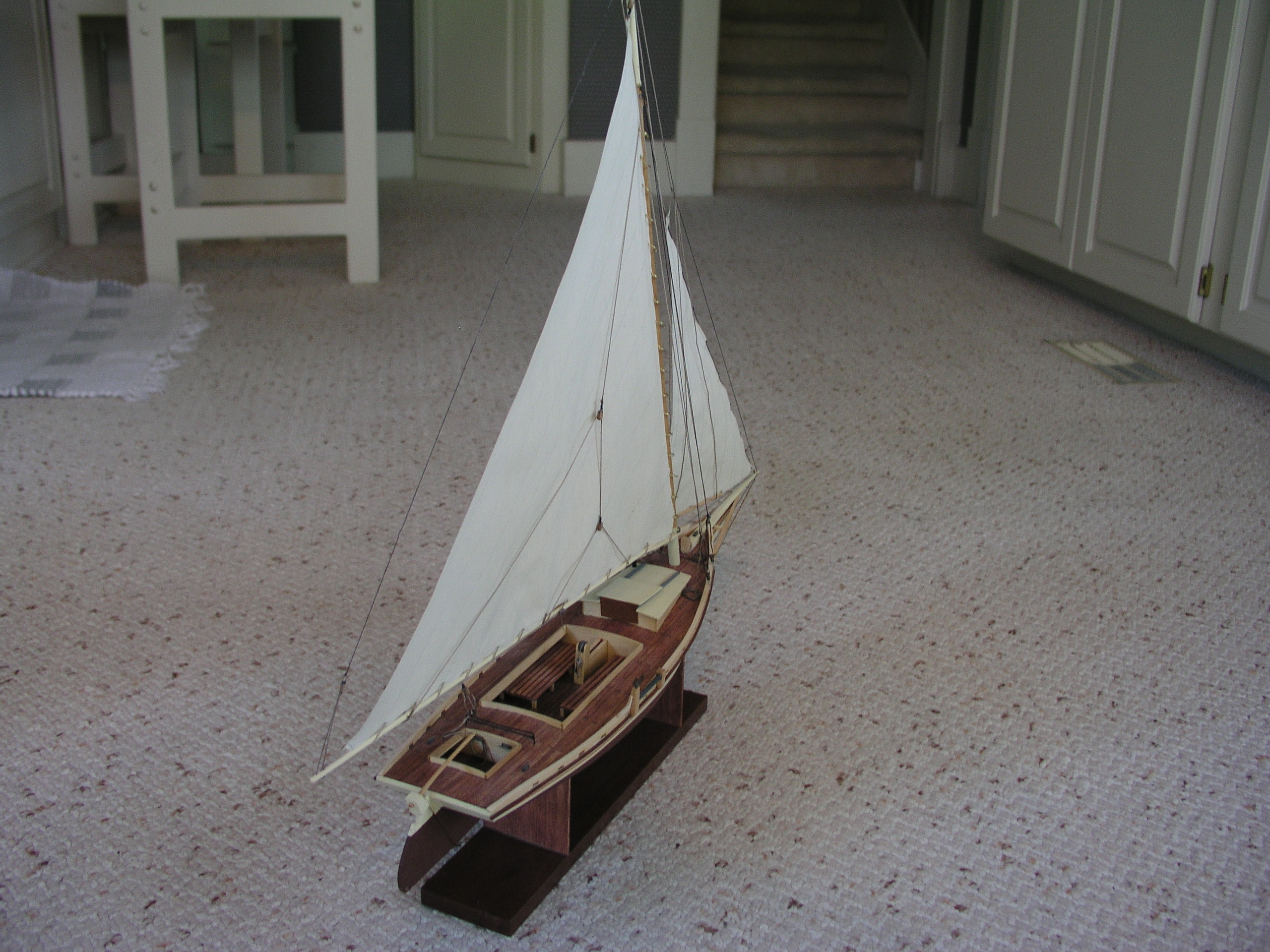
I've always been impressed by well-done ship models. I thought it was time I gave it a shot, and picked out a large and elaborate model kit. Fortunately for me, I let the guy at the hobby shop talk me into trying something a little easier for a first attempt. This was a Midwest Chesapeake Bay Skipjack kit, and I highly recommend it for a first-time modeler. It was sufficiently challenging to be interesting, but easy enough to avoid first-timer's frustration. I also took the liberty of do a bit of customization, building benches out of left-over planking. I gave the model to my folks for Christmas a few years ago, and since then a chunk of it has fallen off. I'll have to bring some glue the next time I venture back to Kansas.
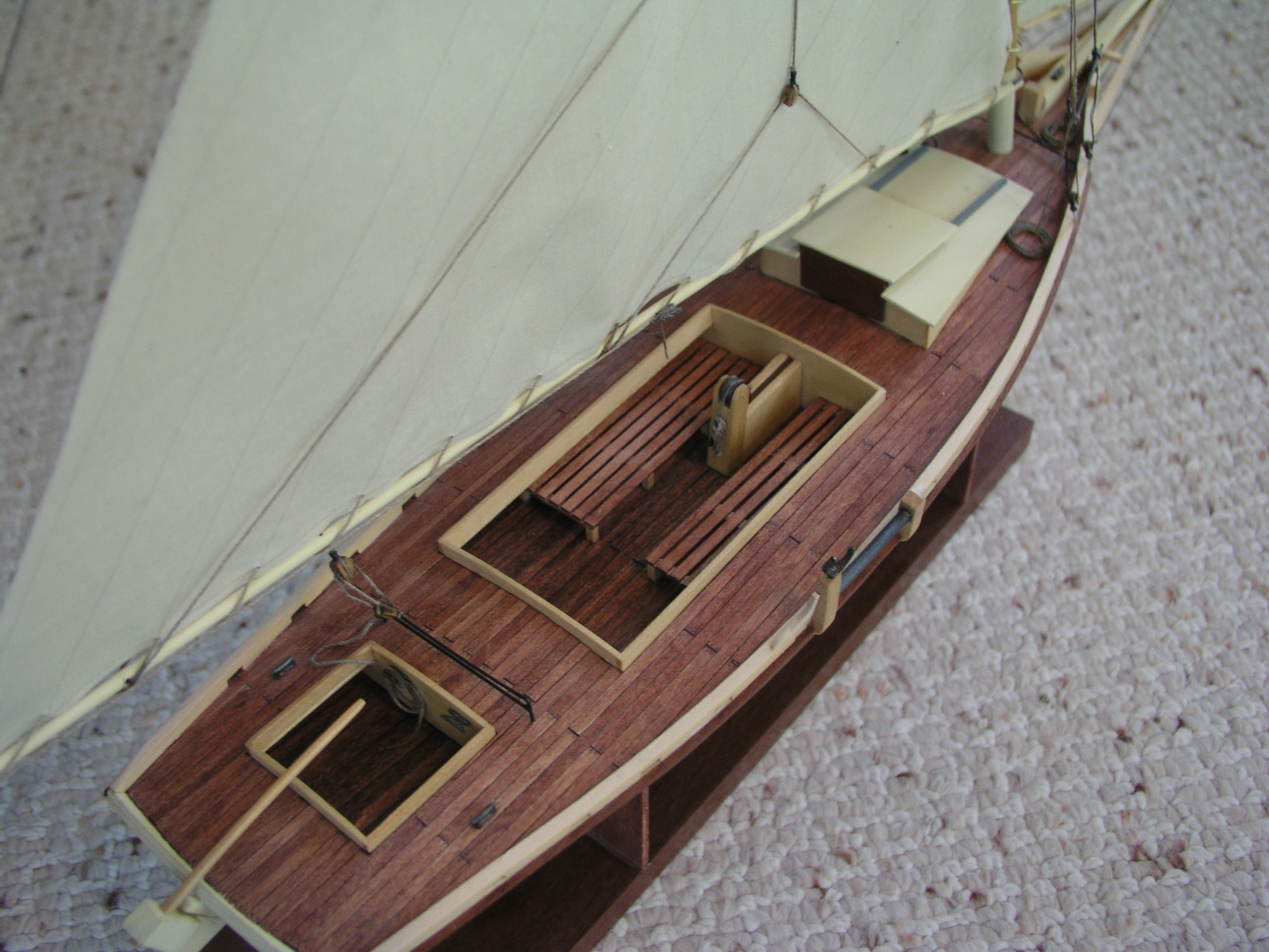
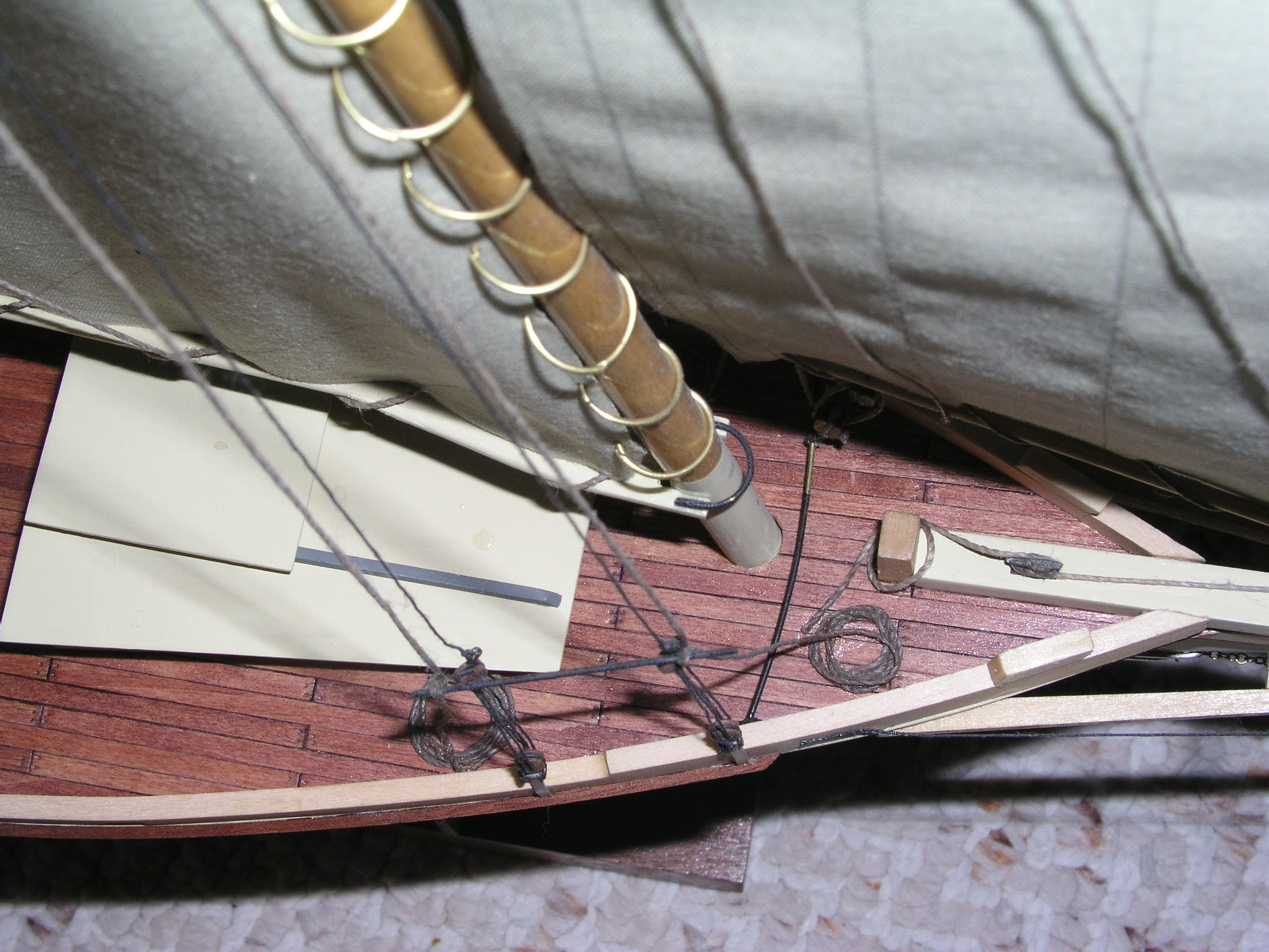
I put a lot of effort into the little details. Click on these photos to get huge blow-ups and see if you can tell it's a model.
I think it turned out well (other than getting the waterline paint wrong...).
If I ever finish Magic-1, I plan on trying a much more difficult one. LCC retargeting for D16/M homebrew computerRecently, John Doran put together a web site with details of his homebrew machine, D16/M. While looking over the instruction set, it occurred to me that it might not be that difficult to retarget LCC to it. LCC is a nice full ANSI C compiler designed to be easily retargeted. For the most part it is, particularly if your target happens to look like a classic RISC machine with an orthogonal instruction set architecture. D16/M is quite different that than - it's a 16-bit accumulator machine, and addresses memory as an array of 16-bit words. To get LCC to work, I told it that D16/M's char, short, int, long int, pointer, float and double types were all 1 byte wide. Additionally, I changed a bunch of places in LCC's source code that had a hard-wired assumption that a byte is 8 bits wide. Instead, I added a field in the interface record to allow a target to specify how wide a byte (i.e. - minimum unit of addressability) is. For D16/M, it is 16, for others 8. The result of this is that D16/M will have 16-bit ints and chars. It could easily be extended to support 32-bit ints & floats and 64-bit doubles. The second big trick was to lie to LCC and tell it that D16/M had 8 integer registers and 8 floating point registers. In truth, these were simply fixed memory locations. Amazingly, it all seems to work. For you LCC retargeters out there, here's the .md file to see what I did. Email me if you'd like more info on the byte width modifications.
|