|
|
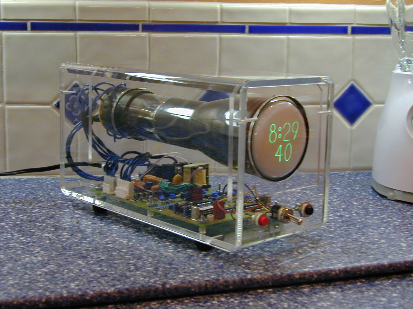
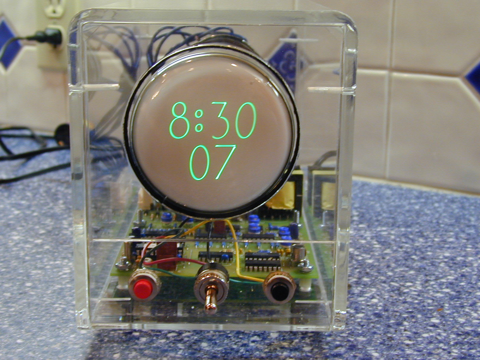
Diary entries for 200312/31/2003Quite tedious, but completed a fresh signal def/use spreadsheet - this time including signals local to each card and analyzing for fanout. Again a bit surprised at the problems I flushed out. Good to get them out, but I'm much less confident in the correctness of everything now. Should have been more stable at this point! Here's the spreadsheeet. Anyway, I identified one completely unused signal - _EL_PTB. No idea why I had that one. The _EL_xxx signals are used to drive register values onto the L bug. The PTB reads from the L bus, but does not write to it. Also, found four more signals that were assigned slots on the backplane, but in fact were completely local to a single card: FAULT_PENDING, PRIV, MSWD and _EL_FCODE. I've removed all five from the backplane. I'll probably allocate 4 of them to power lines, and perhaps restore _HALT on the backplane (in order to bring it out to the front panel). In truth, most of the bugs I've found were pretty benign - wasteful use of the backplane, naming inconsistencies, etc. However, there were some serious problems with fanout. I have eight signals or busses that exceed that standard 10 TTL fanout. About half were correctly buffered, but I had to run a couple of the signals through 74F244 bus drivers to support the fanout requirements. The most serious fault here was that I was not buffering the page number portion of the address bus - just using the raw output of the page table SRAM. That wouldn't have worked at all. Didn't have room on the page table schematic sheet to correct this, so I added a couple of 74F244s on the RAM/ROM sheet. Finally, discovered that I had neglected to generate the _WR signal (which is the clocked write pulse). Added & buffered it on the control card. It's about 10:30 p.m. now. Better get my New Year's glass of wine and relax. Hope to get a fresh (corrected!) set of schematics out by the weekend. 12/30/2003Decided to double-check backplane signals, so I started building a spreadsheet showing for each backplane signal on which card is it defined, and how many uses (per card). Some surprises - I detected a disappointing number of errors. There were a half-dozen or so places in which I named a signal inconsistently or flat-out incorrect. At this point, I had hoped I would have caught those kinds of mistakes. More seriously, it seems I have more of a fan-out issue than I thought. A while back I did a quick check and convinced myself that I only needed to worry about _RESET. I haven't completed the spreadsheet, but it's clear I will have several signals that will exceed the TTL default of 10 fanout. It may be that I'm okay because these signals are already driven by bus drivers (rasing the fanout total to 30 or so), but I'm a bit distressed that I'm finding these kinds of errors at the point at which I thought I was ready to start wrapping wires. I also decided that tweak my signal naming scheme a bit. While doing the signal def/use spreadsheet, it wasn't always obvious which signals were on the backplane, which were local to the card only, and which were destined for the ribbon cables going to the front panel assembly. I think I'll try something like all upper case for backplane signals, all lower case for card-local signals, and mixed case for the ribbon cable signals. In general, I find that a good naming scheme can be really helpful when debugging. It would have been best to have a good scheme from the start, but better late than never. Finally, because I found problems doing the spreadsheet, after I've completed correcting the mistakes and applying the new naming scheme, I'll do a fresh signal def/use chart (and keep doing them until I complete one without finding any new errors). 12/28/2003In the early stages of a flurry of project activity. I've created a new set of schematics, and hope that I'll be making only minor tweaks. Over the next couple of days I'll be updating the simulator to deal with some minor changes I've made lately. After I pass the validation test suite, I'm going to assign packages on the logic card portion of the front panel. The front panel will consist of one of my five wire-wrap cards to hold the logic, plus an assembly that will hold the LEDs and switches. I've decided to push ahead with construction even though I haven't worked out the enclosure issues. During early bring-up I'll be using a temporary front panel (just the required switches and some LEDs). The rationale here has mostly to do with the fact that I simply don't have a lot of space in my house to work. I think the right thing to do would be to build the enclosure and final front panel first - that would give a nice debugging testbed. However, I'm confined to a small desk in the bedroom - and a full enclosure would take up too much of it. Instead, I'll use my card cage as a debug testbed. I'll move to the real enclosure with the real front panel just prior to starting work on the ALU/register card. Speaking of the right thing to do, I really should do more simulation before beginning construction. I have left some space in the ISA for FORTH primatives, and I really ought to define those opcodes and do some more general testing with the C compiler in simulation. However, I think I need to start pushing electrons around. This project has been virtual for a long time. I think once I start seeing real signals it will energize me to get this thing running. So, I hope to begin actual construction within the next couple of days/weeks. I'm going to start with the clock/reset circuitry that's located on the front panel logic card. It should be one of the easier cards to build, and the clock would have to be done first anyway. Should be good for getting my cut/strip/wrap techniques honed up as well and give me the opportunity to play with the oscilloscope and logic analyzer I picked up on eBay. Oh, also plan on doing a detailed bring-up plan. 11/23/2003Added a projects page, breaking it in with the Dekatron kitchen timer I made for Monica a few years ago. I'll add my other projects (including the scope clock below) from time to time. On M-1, I need to update the simulator to reflecdt the changes introduced when I rearranged the backplane signals. The changes shouldn't take long. Doubt I'll get to it before Thanksgiving, but should have it done shortly thereafter. I've got some time off around Christmas, and my hope is to start working on assigning packages to my wire-wrap cards. 11/1/2003This project is such a long-term effort that I occasionally need to take up a quick project so I can have something completed. Over the last week I built a "scope clock" from a kit put together by David Forbes at http://www.cathodecorner.com. It works great, and looks fantastic. David did a magnificent job with it. It's not a vector display, but instead draws the clock digits out of arcs and lines generated by sin and cosign signals with the magic amount of phase shift. Here's some photos (click thumbnails for larger images).
I hope to get back with this project soon, though I'm quite busy at the paying job. Things should calm down there within a couple of weeks. 10/9/2003Bummer. In the midst of a hiring freeze the new job offer got all but the last required signature. Oh well, on the bright side that means I'll be able to spend more time doing really important stuff like this project. 9/19/2003Did a little web searching on special wire-wrap wire for cut/strip/wrap bits. Turns out that OK Industries also makes it. The difference appears to be special insulation which easier to strip. DigiKey had some in stock, so I ordered a couple of small rolls. When they arrive, I'll report on how well they work. 9/18/2003Essentially no progress on the M-1 front. I've been a bit pre-occupied with the paying job issues. On the bright side, it seems to be coming close to resolution. And, whether I accept the new position or stay with the old one I'll be in good shape. There is some minor progress to report: my cut-strip-wrap wire-wrap bit and sleeve arrived in the mail today. They were a bit hard to find, and appallingly expensive. My rationale for buying them rather than sticking with my old plan of using pre-cut and stripped wire is that my cards are going to be so dense with so many wires that I'm going to be faced with a huge rat's nest. I could cut and strip each individual wire to length, but I doubt I could really do all that well manually. The pre-cut stuff is never going to be exactly right, so I'd end up with lots of slack. So, I figured if I could use the fancy cut-strip-wrap bit I could get the lengths exactly right. The bit is used in a slower RPM wire-wrap gun (which Gil Smith gave me). You insert unstripped wire and it cuts, strips and wraps in one motion. You then put the other end of the wire in the bit, place the bit over the target post and pull the wire through the bit until the length is correct. Pull the trigger and magic happens. At least, that's the theory. I tried a few wraps shortly after I got home today and each time instead of doing the cut-strip-wrap, it simply snapped the wire off and jammed a piece of it in the bit. After a bit of frustration (and anger after spending all that money), I thought I'd try some different brands of wire-wrap wire. The first batch was from OK Industries - and it snapped every time. Next was a spool from Page and *yes!* it worked nine of ten times. I also had an unlabelled roll from Radio Shack and it seemed to work as well. I'll need to practice a bit to get it right. The first issue is getting the slack just right on the 2nd wrap of a wire. The bit is a modified wrap bit, which does a couple of turns of insulated wire before the stripped part. I have to be careful that my wire isn't pulled too tightly and I lose all of my slack. In that case, I might be susceptible to the wire getting cut an shorted on the sharp corner of another post. So far, so good. I also ordered a roll of special cut-strip-wrap wire at the same time I ordered the bits, but it's been a month or so on backorder. Don't know if it's even made anymore. 9/6/2003Big changes possibly coming on the paying job front. May mean a bit of a slowdown on this project. We'll see. 9/2/2003Finished the first pass of the schematics changes and backplane signal reassignment. Decided to eliminate _HALT and TRAP_PENDING on the backplane (and front panel). My plan was to make the power/ground assignments the same on both the left and right backplane. This would make things a bit nicer if I decode to make a custom PCB - I can just do two copies of one half. It left me with fewer choices, and I ended up with more ground lines than I hoped. To try to even things out a bit, I punted on _HALT and TRAP_PENDING. On the bright side, it occurred to me that I didn't need the encoder lines on the backplane, which helped a lot. So, I ended up 20 power and 26 ground lines split evenly between the two halves of the backplane. Hope that's enough. I haven't yet transferred the schematics changes to the simulator. Need to be careful doing that. Also, I need a thorough desk check to make sure there isn't a stray signal that crosses boards but isn't assigned a back plane line. Think I'll wait until that's done to upload a new schematics set. 9/1/2003About mid-way through the changes. For the time being, decided to keep both _HALT and TRAP_PENDING on the backplane even though I could remove them. I think they'll be useful on the front panel. That takes me to 19 free lines. Played around a bit with ExpressPCB, and it was quickly obvious that making a custom backplane on a 2-layer board isn't going to work very well. One possibility is to just do power/ground on the custom board and wire-wrap all the signal lines. Another is to see what a 3 or 5-layer board would cost. Or, I could just use what I already have, but with beefed-up power/ground connections. Progress is slowing, as I'm a bit pre-occupied with stuff going on at the paying job. Hope to push to a clean stopping point in case I have to put things on hold. 8/30/2003Made another pass over the backplane signals and identified some miscellaneous lines that could be freed up for power/ground. Here's the current full list:
This puts me up to 20 freed lines to devote to extra power/ground. A possibility here now is for me to make both backplane connectors have the same lines devoted to power and ground - which will make it cheaper and easier for me to do a custom circuit board. Some notes on other signals:
Wondering whether I should do some signal renaming to designate card-local signals vs. backplane signals. As it stands now, I could easily miss something here. In other news, the paying job is likely to ramp up significantly in a few days, so progress on this project will probably slow down a bit. Hope to at least push through these changes. 8/28/2003Collecting notes and todo's for the signal integrity and power distribution rework:
Some TODO's gleaned from reviewing the schematics:
8/27/2003Back from a quick vacation. Just before leaving, spent a bit more than an hour with David Conroy going over the design. Got some great feedback, and as a result will be adding some in-line termination to all clocked signals going across the backplane. Also, I'm going to sacrifice some front panel LEDs in order to free up some backplane signal lines. David suggested that I don't have enough power lines running in, so I'll get rid of 5 of the IR signals, all of the microcode NEXT signals and a few other miscellaneous signals that I only had running out to the backplane for debugging. In their place, I'll space out some additional power lines. I still like the idea of having IR on the front panel, so I'll probably add an 8-bit latch on the front panel card and have it shadow the real IR. I can then use that for front panel display without needing the backplane lines. I will have to eliminate the microcode NEXT display on the front panel, or run a special ribbon cable from the control card to the front panel. For the moment, I'll just plan on getting rid of it. Another suggestion was to generate the clock on the same card as the control signals, and not have it cross the backplane at all. I spent some time looking at this while on vacation and decided I just couldn't do it. I simply don't have the room on the control card. However, I can make things a bit nicer by having the control card be the only consumer of the free running clock. All clocked signals (such as register write strobes) will originate from the control card, and will use the in-line termination mentioned above. All in all, this will mean a fair amount of changes. I'll particularly need to be careful to keep the simulator in sync while I make the changes. I'm guessing this will take me a couple of weeks. 8/17/2003Added real time clock, and reprinted the schematics. Now we'll try the soft freeze again. I think I'll push forward on the hardware front. I've been delaying assigning devices to particular locations on the cards until things firmed up. Well, I think it's safe to start. I've got some color scans in the schematics .pdf of the wire-wrap cards, and my intent is to overlay labelled rectangles representing devices. I'll start with the component side, and then perhaps just use mirror-image printing to print out the wire side. That will guide me in placing the wire-wrap ID tags that I'll be using throughout. I was thinking about the huge number of wires last week. It really has the potential for a horrible rat's nest. There are simply too many wires for me to cut and strip. Although the time it would take is important, the biggest problem is that when I cut and strip wire-wrap wire, I not infrequently nick the wire where I start the cut. With thousands of wires, I'd almost certainly get a break that I might miss. So, I had planned on using pre-cut and stripped wire. The problem there is that the sizes often won't be exact, so I'll have a lot of slack - and however careful I am a rat's nest will emerge. So, I decided to at least try cut-strip-wrap wire-wrap. Gil Smith gave me his old cut-strip-wrap wire-wrap gun (Gardner-Denver, ~2300 RPM I think - slower than a normal gun), but the bit was worn out and breaks the wire it is supposed to wrap. The bit and sleeve work together so that you just insert the wire - insulation and all - and when you pull the trigger it trims the wire to size, cuts the insulation and wraps in one shot. The great thing here is that I would be able to precisely route my wires and get them to the right length without extra slack. I ordered a replacement bit (horribly expensive!), but it's on back order and is estimated to take a couple of months to arrive. I don't want to wait two months before starting construction, though given as busy as i've been with work and home that may be the best case estimate for me anyway. Still, the first card to be built is the logic portion of the front panel assembly. It is also the least dense board, so I could do just fine cutting my on wire for that and using the regular wire-wrap gun. I also need to address the enclosure issue. I've made a couple of passes through some local surplus electronics places here, but haven't found anything that jumps out at me. Jameco has a 19" rack mount enclosure that looks like it might work. If I take an alternate route home from work I pass by Jameco, so one of these days I'll plan on dropping by to look at a sample. I'd want to be able to put the enclosure in a case, rather than a rack (maybe - a rack might also be cool). Here is a nice looking line of cases , though I'm afraid to ask them about the price. 8/16/2003Looking into the real time clock, and in particular the battery backup circuit. There are some fancy ones using ICs that compare voltages of VDD and the battery, and switch over at the proper moment. I think I'll go with something simpler, though - a couple of diodes. This is the approach I used for my Nixie/Dekatron clock. Following the lead of others, I'll use a high-speed diode, 1N4148 between the battery and voltage in of the clock, and a Schottky barrier diode between the voltage in of the clock and the system VDD. On the schematic fragment I found, the number of the Schottky diode wasn't listed. Jameco has a 1N5817 - perhaps this will work. As far as the real time clock device to use, I'll go with the Epson RTC-72421. Looks pretty simple to use. There are more exotic real time clocks with built-in battery backup, but they exist in a wide package and look a bit messier to use. The big question about whether to use the diode approach or the fancier comparitor approach revolved around whether I also wanted to supply backup power to the 32K-byte SRAM. It would be nice - avoiding toggling in by bootstrap each time, but then again that's what I have the shadow EPROM for. We'll go simple for now. 8/15/2003Finished an update pass over the web site. The architecture page is now up to date, though some time I need to re-organize the instruction set list. 8/14/2003Brought the microarchitecture page up to date, with details about the microcode sequencer and a cycle-by-cycle walkthrough of a typical instruction execution. Also added entries on the software page and made some general edits throughout. It also occurs to me that I declared a soft freze of the hardware design just a bit early. I have not yet designed in a real-time clock and heartbeat timer. This should be trivial - I just need to search around for the right clock part. I recall that Jameco stocks some, and I might even have one left over from one of my nixie tube clock projects. 8/11/2003Quite a bit of the web site is out of date - particularly the architecture and microarchitecture pages. It's pretty close, but I need to keep up with it or the updates will get overwhelming. So, today I spent an hour or two fixing up the architectural validation test suite page. 8/10/2003Decided I didn't want to wait until the new assembler is done to start running some C code, so I did a bit of hacking on qas and my lcc retargeting to get things running. Seems to work on simple things - think I'll stick with simple stuff until the new assembler is on line. Here are some samples, starting with the C code of a Fibonnacci generator: int fib(int n) {
if (n < 2) {
return n;
}return (fib(n-1) + fib(n-2)); } int main() {
return(fib(10));
}
Here's the qas listing after processing the lcc output: : | ; Magic-1 assembly file, generated by lcc 4.2
: | _start:
0000 : 7c 7000 | ld.16 a,0x7000
0003 : cb | copy sp,a
0004 : 80 ---- | call _main
0007 : 00 | halt
: | global _fib
: | cseg
: | _fib:
0008 : e5 f8 | enter 8
000a : 7a 02 | ld.16 a,2
000c : b9 0e -- | cmpb.le.16 a,0+4+10(sp),L2
000f : 19 0e | ld.16 a,0+4+10(sp)
0011 : 83 ---- | br L1
: | L2:
0014 : 19 0e | ld.16 a,0+4+10(sp)
0016 : 2d 01 | sub.16 a,1
0018 : c9 0002 | st.16 2(sp),a
001b : 80 ffea | call _fib
001e : c9 0008 | st.16 -2+10(sp),a
0021 : 19 0e | ld.16 a,0+4+10(sp)
0023 : 2d 02 | sub.16 a,2
0025 : c9 0002 | st.16 2(sp),a
0028 : 80 ffdd | call _fib
002b : c9 0006 | st.16 -4+10(sp),a
002e : 1d 08 | ld.16 b,-2+10(sp)
0030 : 9a | copy a,b
0031 : 1d 06 | ld.16 b,-4+10(sp)
0033 : 3f | add.16 a,b
: | L1:
0034 : 0d | pop sp
0035 : 0b | pop pc
: | global _main
: | _main:
0036 : e5 fc | enter 4
0038 : 7a 0a | ld.16 a,10
003a : c9 0002 | st.16 2(sp),a
003d : 80 ffc8 | call _fib
: | L4:
0040 : 0d | pop sp
0041 : 0b | pop pc
: | end
=========================== Fixups =================================
Fixup applied, 2-byte store of 0x0020 to 0x0012
Fixup applied, 1-byte store of 0x0005 to 0x000e
Fixup applied, 2-byte store of 0x002f to 0x0005
=========================== Symbols =================================
L4 -> 0x0040
L1 -> 0x0034
L2 -> 0x0014
_fib -> 0x0008
_main -> 0x0036
_start -> 0x0000
And finally, here's the simulator output after running. Note the result in register A, fib(10) == 0x37: ** ** HALT ** ** A=0x0037 B=0x0015 C=0xbeef DP=0xbeef MAR=0x0008, M=0x0008 SP=0x7000 SSP=0x7000 PC=0x0008 TPC=0x0007 MDR=0x0000 MODE=0x1 Instruction count = 2305, cycle count = 13473 Elapsed time = 8 8/8/2003Added the IDE interface, based on Peter Faasse's work, along with a 2nd uart. I won't be attempting to do any kind of simulation for these (at least for now). When I get around to doing a functional simulator, I'll emulate them at a higher level. Time, I think, to declare a "soft freeze" on the hardware design. Bug fixes only. I'll do some more testing using with C code via my lcc retargeting and then do a hard freeze. Once that's done, all my package names and numbers will be fixed and my "official" schematics will be a .pdf file. Bug fixes will be applied via Adobe Acrobat annotations (though I'll also make real corrections in a copy of the schematic files). I'll assign packages on the cards after the hard freeze, and then actually start construction. 8/7/2003Finsihed up the ISA changes. My encoding is now officially a mess. It all started out pretty clean, but I've had to rearrange lots of instructions. The problem is that some of my microcode relies on opcode bits to identify source and target registers. So, when I needed to add the 8 new 16-bit displacement sp-relative memory ops, I needed to add them in opcode positions where the least significant two bits were 01 (to select SP as the base register). To do this, I had to break up what were once nice groupings of related instructions. If I were to every find the time to do a FPGA version of M-1, I'd want to revisit the encoding. Also cleaned up my old TODO list from the Notes page, which involved fiddling with the logic to ensure that the MSW is not latched in the same cycle that we take a privliged instruction fault. Previously several of the priv instructions would end up stepping on the condition codes if an attempt to execute them in user mode was made. Not really a big deal, but it would be very unclean to not be in a position to cleanly roll back after any fault. Even after adding the new instructions, I'm cleanly passing my validation suite. I thought I might break qas, but as it turns out correct code is generated. However, I'm no longer hitting 100% of the microcode. Qas isn't smart enough to distinguish between all of the different sizes of SP displacements. It will just emit the first one it sees. The new assembler will take care of that problem. Next up, I think I'll go back to the schematics. I want to move the POST-code hex led displays to a different sheet and put a 2nd uart where they are. Also need to add the IDE hard drive interface (on it's own sheet). While this is going on, I'll be thinking about my macro assembler design and also need to spend a little time deciding on special instructions for FORTH primitives. I'm anxious to freeze the ISA, and I've got about 8 unused opcode slots to play with. 8/6/2003Got the tests passing again, and added new tests for the variable shift and lea [ab],u16(pc) instructions. Once I put in the 16-bit displacement SP-relative loads & stores, though, the assember will break. I'm still thinking I'll not bother to fix qas, and begin work on a real assembler. I've been toying with the idea of going ahead and adding a macro processing facility to it. I've never written a macro processor before, but it seems kinda interesting. I should probably refer to the literature to see how it's done correctly, but it does occur to me that it might be a fairly simple thing to do. What sticks in my mind is the way the FORTH dictionary works. When we encounter a macro definition, its text is associated with its name, which is pushed onto the dictionary stack. Each time the lexer encounters a symbol, we search upwards in the dictionary. If we find a match, the text associated with the symbol is pushed into the input stream, and lexing resumes. The macro parameters would be handled in a similar fashion - pushing the formal identifer and it's associated actual text string. I'd have to do a little dancing to associate the arguments (which would be assigned in order). It seems like it would also be a good idea when I associate the macro text with the macro name that in addition to pushing the macro text back into the input stream, that I push each formal paramater name onto the dictionary stack with an initial value. That would allow me to define macros with default arguments. At the end of the macro's scope, we'd pop the argument defintions from the dictionary stack. Nested macros should work just fine, and even recursive ones for that matter (at least I think it would - I'd have to be careful about evaluating conditionals before expansion rather than after). I'm sure it's a lot more complicated than this, but this is starting to seem like a fun problem. On the hardware side, I eliminated the extra logic to support 8-bit right shifts. Turns out just to have been a single and gate and a couple of wires. I also looked at what it would take to put in a zex instruction. Unfortunately, I have hard-wired assumptions that prevent me from latching only the high byte of registers a and b. That would have been the optimal solution for zex - just dump zeroes onto the Z bus and only latch the high byte of the target register. I could still do a zex, but it wouldn't be much more efficient than the "and a,0xff" solution. For the time being, no zex. Thinking about opcodes caused me to remember the "HCF" instruction. That might be the one to add. I don't think I'd want M-1 to actually catch fire after halting, but I could have this instruction raise an external signal like which would set off a fire alarm on the front panel. So, "Halt and Catch Fire" would trap - thus disabling interrupts, and then fall into an infinite and unrecoverable tight microcode loop which continued to assert the front panel fire alarm signal. Or, maybe I should stop drinking wine and go to bed now. 8/5/2003Fixing up the microcode to add the new instructions. Added the variable shift instructions, deleted the old 8-bit shifts (but haven't yet removed the unnecessary logic from the ALU/register card), and added the pc-relative lea's. Still need to add the 16-bit displacement sp-relative loads and stores. My encoding is getting messy. I'm having to move instructions around to reduce the amount of microcode needed for these new ops. I'm really running low in microcode space now. One thing I need to do is look at the existing microcode for common tails. When Iwas first writing it, I thought I had plenty of space, so may not have been as diligent about re-using common sequences. No testing of the new stuff yet. I'll save that for tommorow. Haven't decided yet whether to add an unsigned extend to complement my sign extend instruction. I've decided on the opcode name, though. I've got "sex" for sign extend, so figure I should use "zex" for zero extend. It amuses me. God, I'm such a nerd. 8/4/2003Still writing up notes on the lcc retargeting. Mostly thinking about how to proceed with the assembler. My current assembler, qas, is largely automatically generated. Perl scripts parse the microcode web page and extract the instruction descriptions. These are then converted into a yacc grammar and format strings. This worked reasonably well during the period in which I was making frequent ISA changes. However, it was a bit fragile as it relied on relative instruction position to distinguish between long and short forms of instructions (i.e. 1-byte immediate vs. 2-byte immediate). It was also a bit of a pain in that I was unable to easily support pseudo instructions, and had to fix C bugs that were destined to show up in the yacc grammer in the Perl script that generated it. The latest ISA changes will break qas. I could hack it up to make it work, but it might be best at this point just to toss it and start putting together the real one. qas served its purpose well. Time to retire it, I think. My ISA should be relatively stable now (after I make the batch of changes triggered by the lcc retargeting). I think I'll still use lex & yacc, but with a hand-coded grammar. I will write the grammar such that for each instruction that has multiple variants, it will parse to a single state and recover a pointer to a list of possible instruction templates. Then, when the immediate value or displacement is known, it will select the first template which fits. Or something like that. I also want to leave open the possibility of supporting a peephole optimization pass within the assembler to clean up some of the uglier lcc spill code. Or, maybe have this as a separate program (sharing the yacc grammar). Not sure yet. As far as the a macro facility, I think I'll pass on that for now and continue to specify m4. 8/3/2003The basic retargeting is complete. I'm now writing up my notes on the lcc page. Next up is modifying the microcode and hardware design to account for the changes I've decided on, and I also need to redo the assembler to handle some new stuff. I don't know yet whether I'll try to just tweak qas, or rewrite it. May have to rewrite it. 8/2/2003Spent a couple of hours trying to get lcc to do what I wanted with putting any literal initialized with a code or literal address in the data segment. I didn't find a quick solution, and I'm inclined to look no further for now. I had it mostly working, but then discovered that lcc generates jump tables in .lit using absolute rather than relative offsets. To get back to position indepence I'd need to rewrite the jump table codegen to do pc-relative offsets or to make sure jump tables get stuffed in .dseg. I'm not especially interested in this right now, and am anxious to move on to other things. For the time being, I'll just always combine .lit with .dseg. Inelegent, but problem solved. I can revisit this later, if I feel like it. Note that I still need my lea r,d16(pc) instructions, as well as logic within lcc to ensure that I use the pc-relative lea's when materializing function pointers. It seems to work. 8/1/2003Interesting stuff triggered by the lcc retargeting. I'm in the cleanup stages of the retargeting, and one of the minor problems was that I was not correctly generating addresses for globals that live in either the .code or .lit segment. All addresses on the .data and .bss segments are dp-relative, and I was correctly doing "lea r,xx(dp)" for them. The reason for the dp-relative addressing for data, and pc-relative calls and branches was my intent to support position indepent code. However, as I went to fix the literal and code address materialization, it dawned on me that I don't have ISA support for that. I should have "lea r,xx(pc) to dynamically materialize code and literal addresses - but I don't. In short, all data references are dp-relative, and all code references are pc-relative. This means I should be able to map the same code segments to different processes at different virtual addresses, and locate data segments anywhere so long as I set up dp. However, there is one hitch: intialized pointers. These values won't be known until load time, so therefore must have loader fix-ups generated for them. No problem, this is standard stuff. But - if I am to really follow my position-indepent code strategy, I need to ensure that lcc always places any constant intialized pointer in .data rather than .lit. It would be bad form to require a loader fixup to touch code, and would defeat any shared library scheme. So, to recap I need to:
7/30/2003Do I want to add a negate instruction? Don't expect it will be all that common, but it is somewhat unelegent the way I have to subtract from zero right now. 7/29/2003Good progress on the lcc retargeting. My first cut at 8-bit operations looked pretty bad, as lcc converts all chars to their super-type, which in my case is 16-bit ints. So, when doing char arithmetic, we gets lots of useless sign extends and zero extends. Got some suggestions from Richard Man on how to reduce the problem using special rules. When I get that working, I'll write a more elaborate explanation for the lcc retargeting page. I'm pretty confident that it will work, and we'll end up with quite decent code quality. On the M-1 ISA side, I'm considering some minor instruciton set changes. First, I have 8-bit left and right shift instructions - along with some nasty logic on the ALU card to get the correct bit shifted into bit position 8 on a right-shift depending on whether we're doing 8 or 16 bits shrs. In retrospect, I'd probably be just fine if I only supported 16-bit shifts. What I'm thinking of doing is elimating the 8-bit shifts, along with the ALU card logic. In their place, I'd add 16-bit variable shift instructions. I'd model them after the block copy instructions. You'd put the shift count in C, and the microcode would first test C - if it's zero, we're done and fetch the next instruction. If not, decrement C, shift once and back PC up to redo the instruction. There is one problem here - if a programmer were to mistakenly put 0xffff in C, you'd spend a lot of time uselessly shifting zeroes. One solution to limit the problem is to only use the low byte of C (I can't just use the low nibble because I don't have a way to materialize 0x000f in microcode). However, it occurs to me that I can turn this problem into a cool instruciton feature. If I code the microcode to stop if *either* C is zero or the shift target register is zero, I can not only eliminate the problem of long shift loops, but I can also produce a possibly interesting result. By changing the variable shift sematics like this, you can determine the bit position of the least significant or most significant set bit in a register by comparing the starting and ending value of C. Not sure when I'd use that feature, but I kind of like it. I think I'll do this. Also, while I'm at it I'll see about adding a zero-extend instruction (similar to my sign-extend instruction). I can accomplish the same thing with an and.16 r,0xff - but that instruction takes up three bytes. If I can't make lcc clever enough to eliminate spurious conversions, it would be nice to do them more space efficient. Adding this instruction may not be as easy as it sounds. I have some odd logic to trigger sign extending, and I don't immediately recall whether I can latch only the high byte of a register. We'll see. 7/25/2003Between getting sick and being very busy at work, haven't made much progress this week. I have fiddled a bit with the lcc retargeting, and have decided to punt on my attempt to create a running diary of the attempt. Too much work, and I don't think it would be all that useful to anyone else anyway unless their ISA was very similar to mine (an unlikely thought..). So, instead I'll just use that page to jot down a few random thoughts on things I found useful (or not). Anyway, I've decided to lie to lcc and tell it I have two 32-bit integer registers and 2 32-bit floating point registers. In reality, these will be mapped to local variables in the frame. My lcc retargeting will issue made-up opcodes to manipulate 32-bit ints and floats which the assembler will treat as macros expanding to out-of-line calls. The code generated will be pretty ugly, but for my purposes should be good enough. My ints will be 16 bits, and will use the real register set. longs and long longs will be 32 bits, and float, double and quad will all map to 32-bit floats. Here's a simple example of the output, showing immediate assignments into all basic datatypes. The C source is embedded in the assembly output. The opcodes in upper case (such as MEMCOPY) would be macros to be expanded by the assembler. Note also that for immediates larger than 16 bits, I've asked lcc to put them in memory, whereas for <= 16 bits they are materialized in the instructions themselves. Here's the C source: void empty() {
int i;
unsigned int ui;
char c;
unsigned char uc;
long l;
unsigned long ul;
long long ll;
unsigned long long ull;
float f;
double d; i = 1;
ui = 2;
c = 'c';
uc = 0;
l = 123;
ul = 321;
ll = 4344;
ull = 4342;
f = 1.23;
d = 3.23;} Here's the lcc output: ; Magic-1 assembly file, generated by lcc 4.2
.global _empty
.cseg
_empty:
enter 30
;void empty() {
; i = 1;
ld.16 b,1
st.16 -2+32(sp),b
; ui = 2;
ld.16 b,2
st.16 -4+32(sp),b
; c = 'c';
ld.8 b,99
st.8 -5+32(sp),b
; uc = 0;
ld.8 b,0
st.8 -6+32(sp),b
; l = 123;
MEMCOPY L1,$L2(dp)
MEMCOPY -10+32(sp),L1
; ul = 321;
MEMCOPY L1,$L3(dp)
MEMCOPY -14+32(sp),L1
; ll = 4344;
MEMCOPY L1,$L4(dp)
MEMCOPY -18+32(sp),L1
; ull = 4342;
MEMCOPY L1,$L5(dp)
MEMCOPY -22+32(sp),L1
; f = 1.23;
MEMCOPY F1,$L6(dp)
MEMCOPY -26+32(sp),F1
; d = 3.23;
MEMCOPY F1,$L7(dp)
MEMCOPY -30+32(sp),F1
;}
$L1:
leave
ret
.lit
$L7:
.defw 0404eH
.defw 0b852H
$L6:
.defw 03f9dH
.defw 070a4H
$L5:
.defw 00H
.defw 010f6H
$L4:
.defw 00H
.defw 010f8H
$L3:
.defw 00H
.defw 0141H
$L2:
.defw 00H
.defw 07bH
.end
The interesting test for me will be when I get the lcc retargeting done well enough to start compiling portions of the Minix OS source code. I still have a stretch goal of getting Minix running, and had a brief correspondence with Minix expert Kees Bot on the topic. He didn't directly answer my question: "am I a complete lunatic for even considering this?", but did suggest that one of my problems with a 16-bit port would be the code density of my ISA/compiler combination. Using x86 and the ACK C compiler, quite a few key Minix applications and components just barely fit into 64K of code space. Despite it faults, x86 is a pretty dense encoding, so I can't be sloppy in my lcc code generation. I think M-1 is pretty dense also, so this should be interesting. On the hardware side of the house, I guess I lied when I said the hardware design was complete. I neglected to add the IDE hard drive interface, as well as something for internet connectivity. The IDE stuff appears pretty simple - there are quite a few designs out there for microcontroller and 8-bit computer IDE interfaces based on a 8255. I think I'll go that route. As far as the internet, I think I'll take the easy way out and simply add a 2nd serial port. Assuming I get Minix running, I'll just run a direct serial cable to one of my Linux boxes and use PPP to get out to the world. If I don't get Minix running, I've seen some stand-along little boxes that interface serial devices to the net. 7/19/2003Working my way through the lcc retargeting. Spent most of my time re-reading the important chapters of the lcc book. There are still a few things I'm not sure I know how to handle, but it's all going pretty smoothly. Starting off with addressing, and have the basics working. For example:
compiles to:
I'm not yet worrying about function handling, so you won't see the enter/leave/ret in the above example. That is actually going to be somwhat tricky (have to make sure I'm computing frame size correctly, and will likely need to use a lot of ugly .equ's). Enough for tonight. 7/16/2003No real code changes - just working (mostly on paper) on the lcc retargeting. See retargeting diary for details. 7/13/2003Had a bit of a hiatus here - very busy time at the paying job, two kids with the flu and inside of the house getting painted. Still, some progress. I got some excellent suggestions from Alistair Roe about the enclosure for this thing, which led me to do a bit more thinking about the front panel and backplane bus as well. I'd originally planned to build the case out of tinted Plexiglas to show off the insides, but I now think that would look pretty bad. I think I'll take Alistair's advice and go with standard 19" 6U case. That will give M-1 more of the look and feel of a 70's machine, and give me plenty of room inside. I may end up dumping my existing card cage - which is no great loss. I put a lot of time into wiring the backplane, but it would probably have to be junked anyway. I need to understand the electrical characteristics of the backplane bus better, but what I did is probably lousy. It's clear even to me (now) that I need to handle power/ground better, and after reading a few things on the net I wonder whether I need to do any kind of termination to reduce signal reflection. Will need to recruit a real EE for advice here, I think. On the front panel, I continue to waffle a bit on how to proceed. The basic construction is to put as much of the front panel logic on one of the wire-wrap cards, and then have some ribbon-cable run out to the front-panel assembly (which has the leds, switches and a little bitof logic). Once I start building this thing, the front panel logic needs to happen first. The question is whether to build the real led/switch assembly first, or to just plan on doing a temporary version for bringup and do the real one later. It's tempting to push out building the real one. There may be changes I want to do that won't be apparent to me until I start playing with it. On the other hand, having a solid enclosure and real front panel from the beginning would make construction and debugging go a lot faster. Haven't decided on what to do yet. I've begun the lcc retargeting effort (just a few hours into it), and decided to keep a retargeting diary. It's here. Also put some more thought into a Minix port. Porting Minix to M-1 would be a huge job, and in the end might not work (on paper M-1 is just barely capable of handling it). In any event, though, using the source code of Minix will be a good test of my lcc retartgeting. 6/21/2003WooHoo! Hitting 100% of all opcodes and microcode instructions in my validation suite. That doesn't mean I'm fully tested, though. There are a number of functionality tests that have to be done. In particular, I need to test user/supervisor mode switching, device addressing, sram access, interrupt blocking and proper SP/SSP interaction. I also need to do a cleanup pass on the microcode, with an emphasis on getting rid of tail duplication. 6/20/2003Spent the week at a conference, and had a couple of evenings of bad TV and little interest in wandering the streets of a strange city. So, got lots done. The validation suite is now hitting 100% of all opcodes and 99% of all microcode instructions. All that's left (as far as coverage goes) is the external interrupt requests. I tried to finish those as well by triggering them from the simulator but ran into problems. I need to review my IRQ design - I think there may be some problems in resetting. Along the way, I fixed quite a few problems. Some were hardware design, but most were simply in the simulator (or bad tests). It's looking pretty good. After I get the interrupt stuff done, I'm not sure whether to press ahead with the lcc port or actually start construction on the front panel. Probably do lcc. 6/15/2003Hitting 77% of all microcode instructions now. What's left are traps, interrupts and supervisor mode special ops. I removed the bogus addressing mode instructions and now have 20 spare opcode slots. The bad news is that I only have 26 microcode instructions left, so I won't be able to do a lot of complex ops. However, I figure that a good chunk of those 20 will go towards special-case immediates - such as add.16 a,1 (inc). I suspect I can implement those kind of ops without using any of the free microcode slots. Also, I haven't made a pass over the microcode yet to factor out common tails. I'd guess there are a few that would free up some more slots. So, not too worried. I should be able to slap together a nice set of Forth primitives. Not today, though. 6/14/2003Up past 70% microcode coverage, and have identified quite a few silly instructions. For the sake of orthogonally (sp?) I allowed the same addressing modes on arithmetic ops as I have on loads and stores. Thus, I have instructions of the form:
There's no reasonable way I'd ever use this kind of instruction. Instead, I think I'll remove them and free up some space for new instructions. One obvious group is Forth primitives. Another batch I'd like are store immediate 0 and store immediate 1. Earlier I tried to build a general store immediate instruction in microcode, but I recall there being problems. Perhaps lack of temp registers? Anyway, I'll just nuke the bogus instructions for now and add nops. Another useless instruction was ld.8 c,u8. Don't know what I was thinking there. C is only useful as a count/temporary register. For counts, the full 16 bits is always involved. I think what I really wanted there was ld.16 c,exti8. That makes sense. I'll change it. 6/12/2003Steady progress on the validation suite - up to 56% microcode coverage now. Flushed out a couple of simulator bugs, and one hardware problem. On my 8-bit right shifts I was shifting in the least significant bit of the upper byte of whatever happened to be on the Z bus. I've fixed it in the simulator, but need to add an AND gate to the ALU design. Bit worried about that - I've already used up 69 of my possible 70 packages on that card. Perhaps there's un unused gate somewhere. 6/11/2003Spent a few minutes writing alu tests before heading off to work, and once again stumbled over two's complement overflow computation. For some reason, I never can get this right. The real definition is carry-out of last bit xor carry-in of last bit. Earlier I tried to simplify my alu design by computing this by xor'ng those bits of the result. This works only if you are operating on sign-extended operands - including operand bits in carry position. It doesn't work otherwise, so I reverted to my previous alu design in which I piggy-backed a 74382 on the high nibble of the low byte just to get access to the overflow out signal. There's probably a simpler way to compute this, but it eludes me. I have access to carry-out of high bit of the low byte, but I don't see where I can easily get the carry-in. I'm probably missing something obvious. 6/10/2003It's been fun playing with m4, though I'd probably have to confess that I wasted more time mucking around with macro definitions than I possibly could have saved by just editing the test files directly. Anyway, I like macros, and it works well. I have a single include file that defines macros for test init, unique symbol generation, subtest marking and test end. The way it works, I can assemble a single test, or simply concatenate/include any combination of test files into a single test program. The tests will have to be modified somewhat to run on actual hardware. They actually would work as-is, provided I toggle them into sram. More likely, I'd want to have them burned into EPROM. However, in that mode I'd need to relocate all of the data to the 2nd 16Kbyte section. Not a big deal, but the assembler isn't up to it yet. In other news, I finally got around to adding a microcode coverage option to the simulator. With six sections of tests complete, I'm hitting 27% of all microinstructions. Now, time to go back to writing tests - I want 100% coverage before I move on to the lcc retargeting. 6/07/2003Time to backtrack a little. I've completed the first four sections of the validation suite, and it's getting a little ugly. I thought I might be able to get away with using the C preprocessor to construct my test suite. I'm afraid I need something a little more sophisticated. I just installed m4 and am playing with it. I looked at m4 many years ago when doing a lot of PA-RISC assembly programming. Ended up not using it, though. Anyway, after getting up to speed on m4, I'll redo the test framework. What I hope m4 to do for me is the following:
6/06/2003Slow going now - I'm putting together the validation test suite. My bugs are split pretty evenly between the tests themselves, the assembler and microcode. The assembler is truly a quick hack, and has little to no error handling. Undefined symbols show up as a core dump, and there isn't any checking for when a branch offset goes out of range. I'll need to fix that before I waste too much more time. In other news, I decided to rename my register load instruction to "copy". Also, for some reason I didn't have a copy from SP to A (or anywhere else). So, I burned one of my three unused instructions to give me a copy A,SP. 6/03/2003The assembler, "qas", is now functional at roughly the same level as it was for my previous revision of Magic-1. It's quite a hack, but works. At the moment, it's a one-pass assembler with backpatching to fix up forward references. Also, it's absolute. The listing is generated in the first pass, so forward references show up as "--" in the listing, but the patched values are displayed in the "fixup" section. Here's the listing from assembling the fibonacci generator: :
| ; Fibonacci test program 6/02/2003Decided to go ahead and slap together an assembler. I took a quick look at some existing meta-assemblers, but decided to just re-use the lex/yacc-based one I wrote for an earlier version of M1. It isn't very elegent, but it will work well enough for now - especially because it's a cross-assembler and speed/space are of little concern. The heart of the assembler is the yacc production file, which is autogenerated using a perl script and the opcodes.c file (which itself was autogenerated from the microcode web page here). I simply have a separate production for each of the possible 256 opcodes. For example: ld.8 A,#u8(SP) turns into: | LD D8 A ',' expr '(' SP ')' { gen__u8( 17 , $5 ); } There is a distinct gen__XXX() routine for each combination of offset/displacement/mask (about a dozen). These routines will emit the assembly code. I'm walking a bit of a fine line here with the autogeneration. It's possible I'd be better off just doing the ".y" file directly, rather than indirectly code it via a perl generator script. It's easy to get carried away with this stuff. It's nice that I get a regen whenever my microcode listings change - but it's a pain when I want to work directly with the yacc input file to test things out. Anyway, I'm just at the clean compile stage with dummy gen routines. Unlike last time, I'll go ahead and code support for relocation fixups (last time it was just an absolute assembler). Update: Making good progress. The parser is in pretty good shape, but I've discovered that for all of my compare and branch instructions, I've neglected to put the branch target into the instruction description in the microcode listing.. Other than that, I'm parsing the assembly files nicely. In my earler attempt, I tried to use the parser to distinguish between different immediate & displacement types. It was a mess. Now, all expressions are recognized as "expr", and I'll do the range and error checking in the emitter routines (which have the type info embedded in the name - the __xx stuff). 5/28/2003Home today after taking Maia in to have some teeth removed. Just timed a run of fibonnaci(10), and my simulator is blazing along at 21 instructions per second (this on a 1 GHZ PIII mobile!). Some other stats - I'm averaging just under 6 microcode instructions per regular instruction. That seemed a bit high to me, but fibo is heavy on function call and return, which involves some of the more complex instructions (expecially ENTER). Update: Replaced the logic functions based on NAND2 with lookup tables, and my speed went to 300 instructions per second. Still painfully slow. Haven't yet done any formal profiling. It's about time to build a Linux version of the simulator - perhaps I'll just gprof it there. 5/27/2003Happy tonight - brought up the cannonical Fibonacci generator in the simulator. I had to hand assemble it, and it took a few tries to get right. Along the way I fixed two microcode bugs, one hardware bug and found no new simulator defects. Time now to take a step back and clean up the simulator. It just has one mode now: slow and verbose. I'll add verbosity options to control the output, which will help. However, even with the output trimmed, this thing is dog slow. It took a couple of minutes to compute Fib(10). I'm sure a huge part of the slowdown is a result of my twisted desire to compose all of my logical functions out of a single NAND2 truth table. Perhaps it's time to get serious and replace the composed functions with simple lookup tables. Of course, this is also a good opportunity to check out what sort of profiling tools Visual Studio offers. 5/26/2003 [evening]Go directly to jail. Do not pass GO. Do not collect $200. Uncovered a serious problem with my memory model. For all of my registers, I have the input values set up prior to the rising edge of CLKS. On that rising edge, the new values latch. Without thinking it through, I was also treating SRAM as if it were an edge-sensitive latch. Instead, it is level sensitive - writing when _ce and _we are both low. I had simply caused _we to go low at the same edge that would normally have latched a register value. At the beginning of that period, the memory address and value to write are correct and stable. *However*, once that edge passes, the address bus starts changing to its new value if I also latched MAR on that same edge. And, I do that a lot (perhaps everywhere I do a write). So, writes are corrupted. Not good. After a bit of panic, I found what I hope is a fairly simple fix. If I delay address bus changes until after the falling edge of CLKS, then the address bus will hold its value until the write is complete (there wasn't any problem with dbus holding value - I think...). NOTE: verify no latching of MDR in the same microcode instruction as a memory write. Anyway, what I did was add a second MAR latch (just calling it M for now). MAR is handled as usual - taking new values on CLKS rising edge. It's output is wired to the inputs of M, which latches a copy of MAR on every CLKS falling edge (same as CLKM rising edge). It is the value of M rather than MAR that is then used to feed into the page table circuitry to generate the current address bus values. As far as timing, this has the effect of partially delaying address generation by half a clock cycle., but holding it steady across CLKS's rising edge and following HI period. In truth, though, it isn't until the falling edge of CLKS that all components of abus values are in (code vs. data ptb comes from microcode data - which arrives on CLKS falling/CLKM rising). Now, all components will arrive at that time. Given the speed of my SRAM, I think I should still have plenty of time for memory reads to appear on dbus before CLKS rising. Anyway, good news is that my simulator caught this problem. My earlier one wouldn't have. After adding the new latch to the page table schematics sheet and fixing up the simulator to match, I appear to be correctly executing pushes and pops. It's almost time to handcode a fibonacci generator run it through. Not tonight, though. 5/26/2003Bit of a problem with sign extended loads. I must have planned on having sign extend circuitry in the MDR while writing the microcode, however I didn't include that in the MDR design. I have ALU sign extension capabilities, but after looking at how many changes I'd have to do to the microcode, I decided to add sign extend to the MDR. The reason for not just doing all sign extends in the ALU is that the extend happens at the beginning of instruction sequences. Because I didn't allow for microcode subroutines, that means I'd have to put little trampoline code sections in everywhere (as it is, the sign extended load typically hapens in the first microinstruction - which allows me to branch off to common code following. If it took more than 1 microinstruction to do the load, I'd have to put in trampolines). Anyway, the disturbing thing is that after adding the capability to the MDR, my register/alu card now has 69 packages. I have a hard limit of 70. That's cutting it way too close. 5/25/2003WooHoo! The simulator executed a single instruction (ldi A,0x88) and then correctly fetched and executed a HALT. Lots of little problems fixed along the way, and I'm sure there are quite a few to go. About 1 of 4 problems encountered have been either hardware or microcode bugs, so I consider the simulator a fantastic success. Some of the hardware problems would have been fairly easily found, but a couple were subtle and would have very difficult to track down and fix if they'd made it past the wiring stage. I probably should have coded this thing in Java or C#, but I guess I'm not quite ready to drink the kool-aid. The strong typing would have greatly reduced the problems in the implementation of the simulator allowing me to focus on defects that originated in the hardware design. On the bright side, though, I did find one hardware bug while studying the schematics in conjunction with tracking down a problem that ended up being in software. I'll continue working on this thing an instruction at a time for awhile, but as soon as the simulator seems solid I'll need to get an assembler going. My first assembler for an earlier rev was done with Lex and Yacc, but I've since seen references to a retargetable macro assembler. I think I'll check that out. I know how to do assemblers, so writing another one won't be as interesting as spending the time on things I don't yet understand. Note: One particularly gross problem showed up in the microcode. I defined WORD as 0, and BYTE as 1 - which is how it needs to be for my alu design (selecting result size). However, for determing whether to latch a byte or word for registers A and B I have it backwards: WORD as 1 and BYTE as 0. I've added a second defition of these constants, LWORD and LBYTE for latch operations, but it's unclean. Just note it for now, but I may want to burn an inverter somewhere for consistency's sake. 5/22/2003Tried my first control loop over signal generation, and some problems quickly surfaced. First, (and not surprisingly) my decision to separate signals and busses has bitten me in quite a few places. In short, signals can take any of the 5 state values: XX, LO, HI, UP and DN. Busses, however, are binary. I have conversion routines, but as might be expected I've got lots of places where I'm using levels when I should be binary, and visa-versa. A strongly-typed language would have helped here. The other problem is related. I had a unified array for latch values, but it's clear I need to distinguish between latches holding levels vs. latches holding binary (multi-bit) values. Arguably, the right thing to do here is treat busses and multi-bit latches as bundles of individual level (5-state) signals. However, doing that introduces more problems (as well as runs up against my natural laziness). I think I'll continue along this path for now. The important thing is to keep in mind what I'm losing by using binary buckets for busses and multi-bit latches. I run the risk of missing:
5/20/2003Good progress on the simulator. All of the schematic sheets have been translated to code. Next I need to do a cleanup pass, followed by trace code and finally the outer execution loop. I've written this thing completely backwards. Normally, you'd want to do a vertical slice through the functionality. Get something working on a limited subset and then flesh it out. Because I'm using this for design validation, though, I chose to go completely bottom up. That way I focused on the low-level logic and (I hope) reduced the chance that I'd duplicate a design mistake with a simulator mistake based on a similar misunderstanding. This will make this thing a lot harder to bring up, but that is also a blessing in disguise. I expect that during debugging I'll be forced to look at my logic design in more detail (and different ways) than the desk checks I've done thus far. Bugs at this stage will be dramatically easier to fix than those found after wiring. Whatever extra software pain I go through will be more than made up for later. Incidentally, I've found and corrected about a dozen design flaws during this
process so far - before even a line of my simulator code has executed. The
lastest was not a bug, but a really stupid portion of my ALU design. The
register/alu card was the first one I did, and I remember getting in a brain
knot over exactly how the P and G fast carry lookahead stuff worked (long ago, I
used ot know this, but I'm getting old and senile). Anyway, when it came
time to generate the carry and overflow signals for byte operations, I just
punted and piggy-backed a 74382 on nibble 2 (because it has direct carry out and
overflow signals). All I really needed to do was exclusive or the sign bit
of nibble 2 with the carry-in to nibble 1. Since I haven't used any other
XORs on this card, this won't save me any packages, but it's much cleaner (and
has fewer wires). 5/16/2003I shouldn't be, but continue to be embarassed by the code I'm writing for the simulator. All of the simulators and emulators I've done in the past have been focused largely on performance. This is going to be a hideously slow beast. I keep telling myself that it's okay - the purpose is validation, not speed. Still, though, it hurts to continually recompute signals, avoid factoring out common routines, etc. Having everything repeated and explicit is better for validation purposes. On another simulator topic, I'm still a little unsure about how I'm handling signal levels. Because of the troubles I ran into with the first simulator in regards to ordering of operations and only having hi/lo states, I've been trying to eliminate order dependency in signal generation. The plan is to loop over a signal gen phase until all signals stabalize. Then, inject a rising edge into the clock line and do one more signal gen pass to propogate the edges. Following that, I do a latch pass to trigger any edge-sensitive components. Finally, I massage the raw signal array and convert all rising edges to HI and falling edges to LO. There are several problems with this scheme. First, I only allow edges to appear during the edge phase. An alternate method would be to inject edges anywhere and anytime a signal transitions between HI/LO. I may give this a try, but I worry about timing. This scheme assumes that my edges will eventually go low or high, but I wonder if the way I generate signals might not keep the conditions that caused the initial transltion around for the second pass (which would drive the rising edge all to way to high, or falling edge to low). The other issue with my plan is that I have only one signal generation pass to fully propogate the edges to the consumers. This sends me back to the case in which I need to worry about signal generation order. After some thought, I think I'll stick with the plan, and go ahead to impose an ordering which guarentees full clock edge propogation in one signal generation pass. Although this is somewhat unclean, it does have the benefit of forcing me to carefully consider the edge propogation pathways. Given that my simulation is not taking any notion of timing into account, this edge path desk check might flush out some timing related defects. There really aren't that many distinct edge-sensitive components in the design, so it may not be too bad. 5/15/2003Continued fiddling with simulator, and am already finding bugs in the logic design. I'm taking the approach of translating each sheet of the schematics into simulation code at roughly the TTL package level. This is forcing me to do a reasonably detailed desk check of the logic, which is a good thing. I've completed the signal generation and latch updating for the control card. It's really gross code - certainly not the way I'd do things for a functional simulator, but as far as the goal of using the process to flush out hardware design bugs it's working well so far. 5/12/2003Not much progress on the simulator. Been a bit busy with the paying job (and the kitchen remodel is now complete, which means lots of moving stuff back in and endless chores around the house). However, I did find the time to start doing the defines for my logical functions using a single NAND2 logic table. I just took a look at a disassembly of the code generated for a 4-input nor and it's really gross. Not so gross that I'm going to change anything, though. I continue to be amused at the thought of composing all of my logical functions out of 2-input nands. 5/8/2003Quite a bit of thought on the simulator - too much for a simple diary entry, so I've added a braindump here. Actually started to do a little coding on the truth tables for signal functions. I'll have 5 states: high, low, rising edge, falling edge and undefined. I started writing and/or/nand/etc. lookup tables, but then a line from an old computer science lecture bubbled up from deep in my brain: "with only nand gates, you can build all of the other logical function". Of course, doing so would be extremely wasteful and stupid. However, the thought amuses me - so that's what I'll do. I've got a single nand2 logic table (5x5 array), and then defines based on it to build all the other logic blocks. 5/6/2003I was supposed to take a break, but momentum has pushed me a little forward. Decided to turn to the dark side and use Microsoft's Visual Studio to build the simulator, rather than gcc on Linux. The reason is that I need to become adept at using VS for my job. So, I've started by porting over the utility program that generates the PROM data files from the web page's microcode listing. I had to muck around with my perl script, and it seems to work fine when I do things by hand. Visual Studio appears to have a make-like facility to allow me to generate my files using the perl script, but I've yet to figure out the magic incantations. Guess I'll have to read the man pages. 5/3/2003I'm declaring the initial hardware design complete. I didn't bother to assign chips positions on the cards - that will come after the hard freeze. Now I'm going to take a bit of a break from the project. When I pick it up again, I'll start with a simulator rewrite. Enough has changed that it isn't worth the effort to try to fix up the old one, and besides, I want to structure this one as closely aligned with the hardware design as possible. I've also done a first cut at the front panel layout, and have included it in the design pdf file. It looks like I may have forgotten the push button for front panel memory write. Also, some version of my drawing didn't include a memref led. There is also the problem that I am not leaving enough room for the rotary switches in the center control box. 5/1/2003Nearing the end of this latest burst of work on the project - the kitchen remodel is close enough to complete that we'll be wrapped up with moving stuff back in. The hardware design is complete, except for adding some LED's and drivers in the front panel section. I've done a mock-up of the front panel, but it's not good enough yet to spend the time drawing it in a program. It has caused me to think a bit more about how I'll use the front panel. The one change is that I'll enable the switch to drive the L bus lights on either _DMA_ACK or when I throw the stop clock toggle. All it took was adding a single nand gate (and sending one more signal across the backplane). The plan is to finish off the last of the front panel schematics (but not necessary the LED/switch layout) while this stuff is still fresh in mind. After that, I'll probably take a break for a month or two. When I start up again, I'll redo (or just completely rewrite) the simulator. This has been a really good burst of work. I'm starting to get confident that I'll actually get around to building this thing. 4/26/2003Cleaning up lots of loose ends. Fixed the shift and W[CD]PDE
microcode, and have done several rounds of schematic desk checking for signal
generation. Hope to finish the hardware design this weekend - it's the
last weekend before the kitchen remodel is complete. One that's done, I
doubt I'll have much free time for awhile. Just had an in-the-shower revelation: I have _DMA_REQ in the trap section, as opposed to interrupts. This means that DMA_REQUEST will abort the current instruction, rather than wait for an instruction boundary. This is wrong. I wanted DMA_REQ to be non-maskable - hence the placement with the traps. However, the state rollback strategy cannot deal with asynchronous aborts. So, I still want _DMA_REQ to me non-maskable, but it needs to show up in the interrupt section. This is easily done. I'll or _DMA_REQ with the interrupt enable bit in such a way that _DMA_REQ will force interrupts active. I needed to invert _DMA_REQ to make it's sense match MSWE, and I went ahead and did this with a 2-input nor gate with both inputs tied together rather than an inverter. The reason is that if I should choose to make _IRQ0 non-maskable in the future, the hardware can be set up with a single wire [replace on the the _DMA_REQ inputs into the inverting nor with _IRQ0]. I'd still have to fix up to microcode for this to work. 4/25/2003So I don't forget: There is a problem with INIT_INST. I'm overloading this one a bit much. I need to include this in the MEMREF signal generation, because it latches the opcode into IR. However, I also use it during interrupt handling to commit state. I had thought it was okay, since latching crap into IR at that point wouldn't hurt - but it does hurt to do a MEMREF trap check. I need to use INIT_INST only at instruction start, and come up with a variant to deal with interrupt state commit. There's plenty of room in the MISC field encodings. Ideally, would be able to use a different field so I could do an INIT_INST and COMMIT_STATE at the same time. Also, the MEMORY bit needs to be redone to take the front panel MEMORY/DEVICE select switch into account. Finally, I am nowhere generating the MEMREF signal. 4/22/2003Mostly busy with real work (and now that the kitchen remodel is nearing completion, I'm going to be swamped with rearranging the house...). One thought, though. While working out the page table design, I saved a couple of inverters by having the page present (P) and writable (W) bits low-active. Changed my mind - I'll go ahead and burn the inverters to make them normal. Software convention is positive logic. I thought about changing the names to reflect the sense (NP - not present and RO - read only), but I like P and W better. It's also kind of a nice thing to be able to initialize a page table entry with zeroes. Worth the inverters - back they go. 4/21/2003Working on the page table - just some quick notes: the page present (P) and writeable (W) bits in the page table entry are low active. The memory bit (selects for memory or device) is called Memory and is high active. The M bit is functionally a 23rd address bit. Should I explicitly treat it that way? Need to do the WPTE microcode. It looks like the best way for this instruction to function is as follows:
4/17/2003Busy with paying work lately, so little progress. Some additional thought on the front panel. The spaces on the wire-wrap card that I'm planning to attach the ribbon cables will allow for, at most, 128 signals. However, unless I cut down the sockets, I'm going to have to use smaller ribbon cable sockets - probably 50-line rather than 64-line. In any event, I will need more than 128 lines, so we'll have to distribute this stuff across more than one card. The best candidate is the peripheral card - for now all I have planned for that is a uart. I'll move the address and data switch banks there, along with MAR displays (or something like that). I want to avoid feature creep, but I may go ahead and assign the data bus switch bank an I/O address, and put in the appropriate decoding. Or not - we'll see what it takes. 4/14/2003Thinking some about the front panel. First off, I've confirmed to myself what kind of a front panel I want: mostly decorative. Old computer front panels were used for debugging programs, but really all I expect to do with mine is do is bring-up debugging and then wow everyone with all of the blinky lights. Most of the serious debugging will happen in simulation and with a logic analyzer. For a more functional front panel, I'd need to be able to read the switches like a register - and then have some actual code to enable front panel features. My front panel will be strictly hardware, with (almost) no software involved. However, unless I can toggle in a bootstrap program, it isn't a real front panel - so it will have to do that. Here's all of what I plan it to do:
The front panel will consist of one of the wire-wrap cards with a much of the circuitry on it as possible, feeding into a pair of ribbon-cable headers that lead to the LED and switch assemblies. I don't know exactly how I'll construct the facade, but I sure like what John Doran did with his D16/M. I expect I'll end up with somewhere in the vicinity of 120 LED's. I probably should get colorful, but I think I'll stick with red. Lots of red LEDs. I also thought about adding an instruction single-step feature. I think this would be nice, and could fairly easily be extended to run until the next interrupt, instruction boundary or other event. However, I've got to avoid feature creep if I've to have a hope of actually constructing this monster. I'll pass on that for now. 4/13/2003Decided to move the clock/reset circuitry to the front panel card. Mostly, the control card is filling up, and I don't want another super-dense card (like the register/alu one). There isn't going to be much on the front panel card, and this also will allow me to avoid having to run all of the signals from the switches to the clock select, clock toggle, clock stop, etc. across the backplane. They can go from the front panel wire-wrap card via a ribbon cable to the perf-board on which the switches & LEDs will be mounted. This means the control card is now nearly done. The latest there is the addition of pull-up resisters to the IRQ lines. All that's left now is adding some labels on lines going into busses and some more desk checking. Okay, just added the signal labels to all of the schematics for the control card and review the labeling on the register card. For the most part, I'm consistent with bit numbering: all bit fields use my 0->MSB numbering, while the TTL parts use 0->LSB. I just wire things up right, so it works out. I was, however, inconsistent with the register parts. Most (but not all!) of these store the MSB of on the bus/field into the LSB of the TTL register device. This doesn't matter at all in practice, so long as I'm consistent. The question is whether I am better off renumbering for complete consistency. At the moment, I'm inclined to leave it as it is. Renumbering would mean labeling most significant bits from right to left on the schematics. I think it reads easier from left to right. I could redo the sheets in question with the devices flipped, but that's extra work with little added benefit. May change my mind later, but lets just go with what we've got for now. This means: register and control cards now complete! Next up: front panel. Update: A bug occurred to me while giving the kids a bath - I had hoped to avoid doing a comparison of 0xff of the next microcode field (which signifies usage of the IR value as the next microcode instruction address). The trick, I thought, was that I could just use MISC[INIT_INST] - which is the microcode state which signifies the beginning of a new instruction. The problem is that I also use INIT_INST to commit register state during interrupt handling. So, back goes the comparison to 0xff (which is just a single 8-input nand package). 4/12/2003Finished up the schematics for IRQ and faults. I'd previously assigned microcode state (misc field) for syscall, breakpoint and halt. Really, there was no need for this. I can do all I need programmatically via the microcode. I decided to keep the microcode state for halt (to drive a front panel led). I removed the state for syscall and breakpoint. Oops - yes there was a reason. Have to remember to not be so quick to delete stuff. Even though I can branch to the syscall and breakpoint microcode, I still need microcode state and hardware in order to correctly latch the trap vector into the fault code register. So, I've put back the microcode MISC states for syscall and breakpoint. Might as well note here that the difference between the handling of the two. Breakpoint asserts MISC[M_BKPT], which feeds directly into the priority encoder. When it traps, we'll roll state back to the beginning of the halt inst. For syscall, though, we have a parameter (the syscall number) we want to pass in A. [Might want to change this later]. Also, it would be better to not back up to the beginning of the instruction. So, for syscall we do a 1-byte immediate load into A, then do an MISC(INIT_INST), which will commit the changed state. [IS THIS TRUE? I've since piggybacked a lot of stuff on INIT_INST, so make sure it's still valid to do this. I do the same trick with interrupts. Perhaps I'll need a different MISC state just for this?]. OK - just checked INIT_INST usage. TPC is latched off of the Z bus, so I need to add TO_Z(R_MAR) to all interrupt vector microcode which wants commit current state. It will also latch crap in IR, but that's okay at this point. The other side effects of INIT_INST are also okay, I think, but best keep that in mind. 4/11/2003Well, the bad news is that I'm an idiot. The good news is that handling the interrupt request lines is trivial - just a D flip-flop with D tied active and using the clock input to latch the IRQ. Q then feeds into the priority encoder, and a parallel decoder resets the flip-flop (or _RESET) when the interupt is accepted. Some nice touches are to use the (NEXT==0x0) line as an input enable to the reset demultiplexer, and to handle interrupt masking by using the MSW interrupt enable bit as an output enable on half of the priority encoder. That last part assumes some reorganization of the interrupt and trap lines. Previously, I had fetch, halt and 6 IRQ's in the lower 8 lines, and 1 IRQ plus the traps in the upper. Because if no input is selected, we get all 1's by default, I can have the lower 7 priority lines be all maskable interrupts. Halt doesn't need an interrupt line - I can just send it into a tight microcode loop. I'll still keep the _HALT microcode bit to be used on the front panel. I'll need to redo the microcode for halt. It will simply back up PC and then to go fetch. If I were to simply put it into a true microcode loop, I wouldn't be able to break out of it via an interrupt. By doing the re-execution trick, it gives me a clean instruction boundary in which to accept interrupts. I find it somewhat elegent to use a HALT instruction as an idle loop. I also consolodated some of the register card schematics - now it all fits on 4 pages. Perhaps this weekend I'll find the time to do the schematics for the interrupt and trap stuff (it's just notes now). 4/10/2003Spent some time iterating between the backplane signal assignment and the microcode/field decode portions of the control card. Also finsihed off the new naming scheme - much better. I still haven't decided what I'm going to do about bit numbering. I think my brain is hardwired to (bit0 == MSB). Perhaps I'll number bit fields my way, and just pay attention to mapping them onto the other scheme in the schematics. No matter what I do here, I'm begging for a mismatch. Next up will be either trap/interrupt circuitry or clocks. I've already worked through clock/reset generation a while back, so it will be mostly a case of remembering what I did. As far as the interrupt stuff goes, I expect to thrash a bit. I tried working through it earlier, but keep confusing myself when it comes to interrupt requests. I need to allow an external event to tug the line low, and then have my circuitry release the request when I decide to handle it - regardless of whether the external event has released the IRQ or not. Then, I don't want to accept a new interrupt request for that line until the external agent lets go of the line before pulling it again. I'm sure this is a simple digital deisgn problem - it just isn't obvious to me yet. My earlier attempts ran me off into excessively complex weeds. 4/8/2003One big difficulty in doing a hobby project like this is that after I pick it up again after a break of weeks or months, I end up spending lots of time just trying to remember where I was when I left off. This diary, along with the other docs, helps - but only if I write stuff down. I made some progress yesterday, but most of my time was spent trying to figure out what the MSW[IN_TRAP] bit was for. I vaguely recall putting it in, and that it had something to do with managing SSP - but I found next to no documentation. Anyway, I did figure it out - and now I remember. Better write it down now:
While speaking of traps, remind myself that I need to decide what is the base of the trap vector. The "fault_code" register latches the fault number. I will wire it up to have a fixed left shift to allow room for a direct branch. Note that instead of a trap vector filled with addresses, I'm actually using it as a jump table, so will need to allow 4 bytes per entry for a direct branch. I don't remember why I went this route, but I suspect I ran into difficulties in loading the branch address and took the branch table route. Anyway, I also need to decide where the vector/table will reside. I've currently got all of the high bits of fault_code tied low. I should tie some high to fix the table. Probably but it at 0x100 or something - or maybe at the top of the first 64K. NOTE: Review fault microcode to see if I really need to use a branch table rather than traditional interrupt vector. Something else I ran into was an error with my handling of _SET_FLAGS. I was using this to select whether to latch the ALU flag bits or bits from the Z bus into the condition code nibble of the MSW. However, I notice that when I wrote the microcode I assumed that _SET_FLAGS is also an implied latch of the MSW's ccode nibble. So, the L_MSW signal must be defined as the following function:
Finally, one more note on not writing things down. The circuitry for selecting the input carry bit on the ALU is weird. I spent a bit of time staring at it without having a clue what it was doing. A quick review of my diary and notes was unhelpful - but after I while I remembered. When I don't want to use the C bit as input, I want the incoming carry to be 0 for add and 1 for subtract. In an attempt to be efficient, I'm using a direct bit from the IR - which happens to be 0 for the encoding of add, and 1 for the encoding of subtract. I'm sure it seemed clever at the time, but undocumented cleverness is always stupid. 4/7/2003Updated the schematics for the register and control cards to reflect the new signal naming conventions. Still have to do a round of desk checking to make sure I've got the sense right, and then have to update the microcode listings and the rest of the web site documentation to get back in sync. Also fleshed out the miscellaneous control signal generation on the field decode page. I'd forgotten that I was using 0xF as special codes for both the latch and l-bus enable fields. When 0xf, that means to use some bits from the opcode in the IR to select the appropriate registers. I added mux's for that, but need to desk check. I continue to debate whether to change my notion of bit ordering. Where I'm currently leaning is to redo the ordering in the schematics to use lower-number -> less significant bit throughout, but to retain my lower-number -> higher significant bit in the architectural documentation. This seems pretty bad, but at least I'd be consistent within each domain (and would make a point of calling out the differences - perhaps do a mapping document). Still pondering... 4/6/2003Decided to bite the bullet and rename all signals to reflect high/low active state. I'll prepend an underscore to all low-active signals. Also, I've typically used a convention like MISC[INIT_INST] to refer to the decoded INIT_INST control signal. Instead, I'll refer to the 4 MISC microcode bits as MISC[0..3] and all decoded signals will be given their true name. For example, instead of MISC[INIT_INST] I'll use _INIT_INST (it's low active). I've been hesitant to do this becasue of laziness, but better burn a couple of hours now rather than spend days trying to track down a logic error caused by confusion over signal sense. 4/5/2003As I continue to work through the schematics for the control signal generation card, I've had to think a bit about the front panel. I want a front panel that's flexible enough to view register contents, but with a minimum of exposed control signals. What I've decided to do is have my primary register data display be 16 LEDs showing the contents of the ALU's L bus (which is brought out to the backplane). The driver of the L bus is selected by a decoded 4-bit microcode field. I'm augmenting this by adding a quad 2-1 mux above the L bus field decoder, where the alternate input is the output of an encoded rotary switch (several of which I have left over from my Nixie tube clock projects). When the front panel is active (known by the "DMA acknowledge" signal being asserted), the field decoder uses the output of the switch to select which register is driving the L bus. Otherwise, the microcode chooses. This is half of a good solution. The problem is that when the machine is running, the register display LEDs will just flash around and you won't be able to tell what they are displaying. To solve, I'll hang a pair of 8-bit transparent latches off the L bus, which will in turn drive the LED's. To activate the latches, I then add a 4-bit comparator above and below the MUX going into the L-bus field decoder. When the register selected by the rotary switch matches the output of the mux, the latches will grab the data on the L bus and display to the LEDs. When the front panel is active, this means that the L-bus and displays will always follow the switch. During normal execution, the latches will grab the value of the selected register whenever it is placed on the L-bus. This means that we can't be sure that the initial value of the LEDs will match the switched value, but in practice it generally will (and I could always briefly go into front panel mode, set the desired register, and then resume execution. In that case, we're guaranteed that the LEDs will follow the proper register. Speaking of the front panel, I'll also have a rotary switch to select the clock frequency. I want the following clocks:
Given that I want 5 speeds, I'll go ahead and use an 8-1 data selector and add a few more fixed clock speeds. I will use two crystals, representing my max speed (6 MHZ) and my normal speed (4 MHZ), and then use dividers off of those guys to give me lower speeds (3 MHZ, 2 MHZ and 1 MHZ). For the slow variable, I will be using a standard 555 timer circuit - with the added enhancement of a rotary pot that is labelled 1 to 11, rather than the puny 1 to 10 labels of inferior dials (ref: "Spinal Tap"). The external input will be used with a function generator to see how high I can push the clock. The clock circuitry is a little tricky. I want to be able to switch clocks on the fly, so I need to guard against puny cycles being generated at switch time. More than a year ago, I think I had this worked out (with assistance from Gil Smith). I hope I can decipher my notes. As for the rest of the front panel, I've have LEDs for the MAR, the DBUS, and several groups for microinstruction address and control signals. I mostly expect the front panel to just look cool with lots of blinky lights, but it wouldn't be a real computer unless I could toggle in a bootstrap program. So, it will have a bank of toggle switches to select a memory address, and another group of 8 for writing memory. I haven't decided yet whether I'll allow the full 22-bit address range of the machine to be selected via switches, or just the low 64K bytes. Anyway, I'll do more work on the front panel later - I want to finish the control signal generation first (but not today - Kansas is playing Marquette in the first game of the Final 4. Go Hawks!) 3/30/2003I've had a streak of little progress on the project (kitchen remodel & busy with the paying job...), but things are picking up again. The impetus was seeing some sketchy info on John Doran's D16/M homebrew. Gorgeous machine - I'm inspired again... Anyway, over the last couple of weeks I've finished off the schematics for the card holding the registers and ALU and am about halfway through the schematics for the control/microcode card. Those are the two most difficult cards, so I can finally see light at the end of the tunnel. Some random thoughts:
The plan now is to finish off the schematics, and then do a new simulator. I'll code the simulator as something between gate-level and functional. Structurally, it will be broken down into modules matching the cards, and will advance state on clock rising edge, high, falling edge and low. Once I validate the microcode and basic hardware, I can do a fast functional simulator. This would be a good time to recap how the microcode sequencer works (since it's fresh in my mind). This particular section of M1 has been one of the most often evolved. I originally started off with a really complex sequencer. It had a microcode program counter, an incrementer, a microcode stack and a whole bunch of logic to support conditional branches. Over time, I managed to vastly simplify it. The primary simplifications were made possible by my decision to go ahead and burn microcode bits and use duplicate and verbose microcode instead of allowing reuse via microcode calls and returns. Thus, the stack went away. I then chose to put a "next" field in the microcode, so each instruction explicitly pointed to the next. This allowed me to eliminate the increment circuitry. The final simplification was enabled by my realization that I could code all of my conditional microcode to always have condition points go either to the next microcode instruction or to the fetch cycle of the next instruction. This was important in that I didn't have to support two condition tails. There were only a couple of cases in which this decision resulted in less efficient microcode sequences, but it really simplified life. I'm really pretty pleased with how it ended up. Here's a summary:
Diary entries for 2002 |