|
|
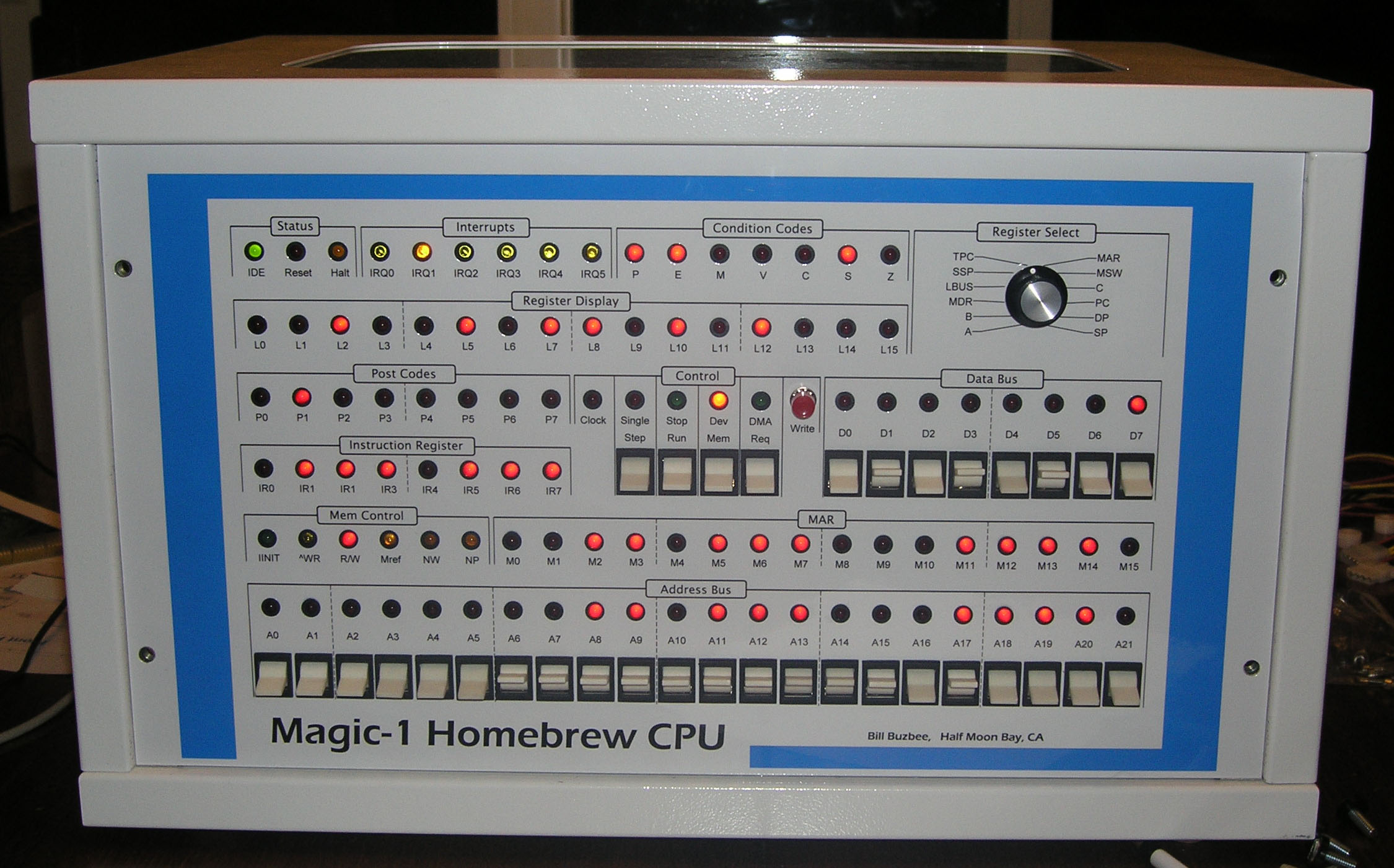
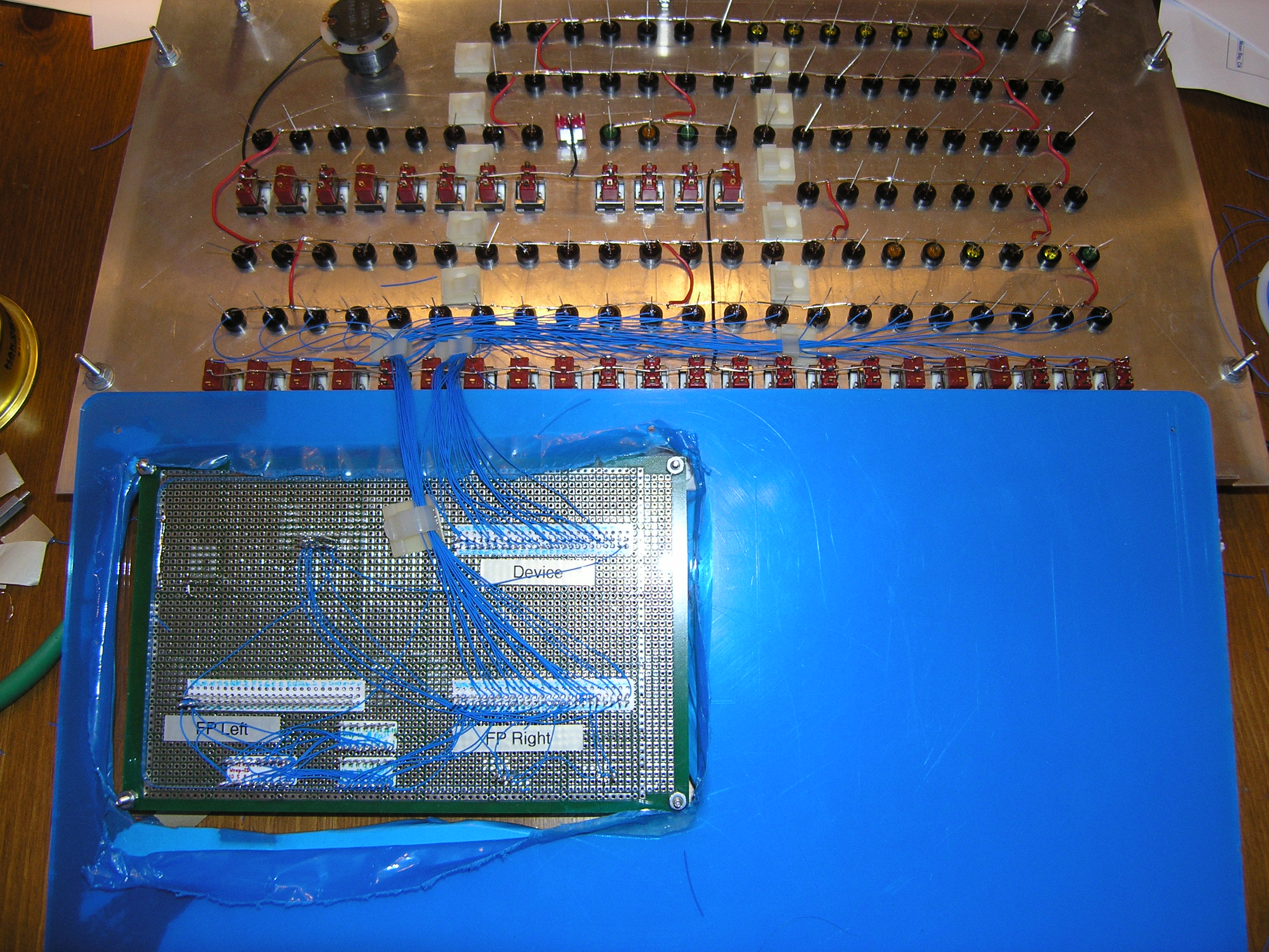
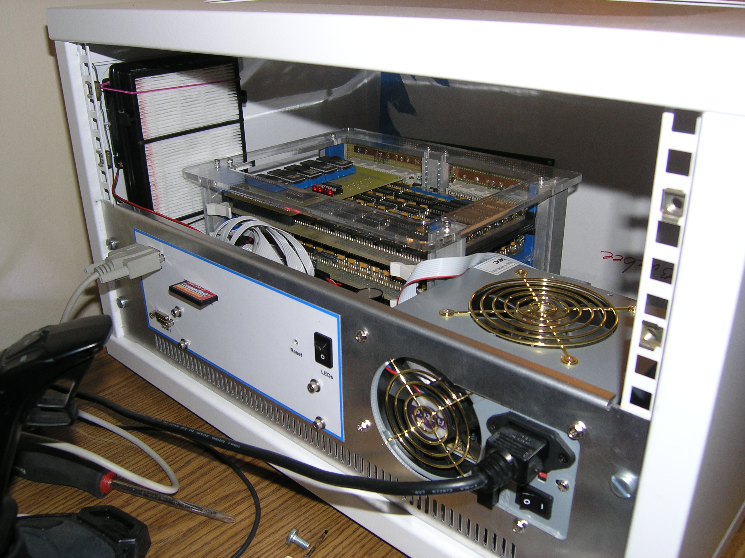
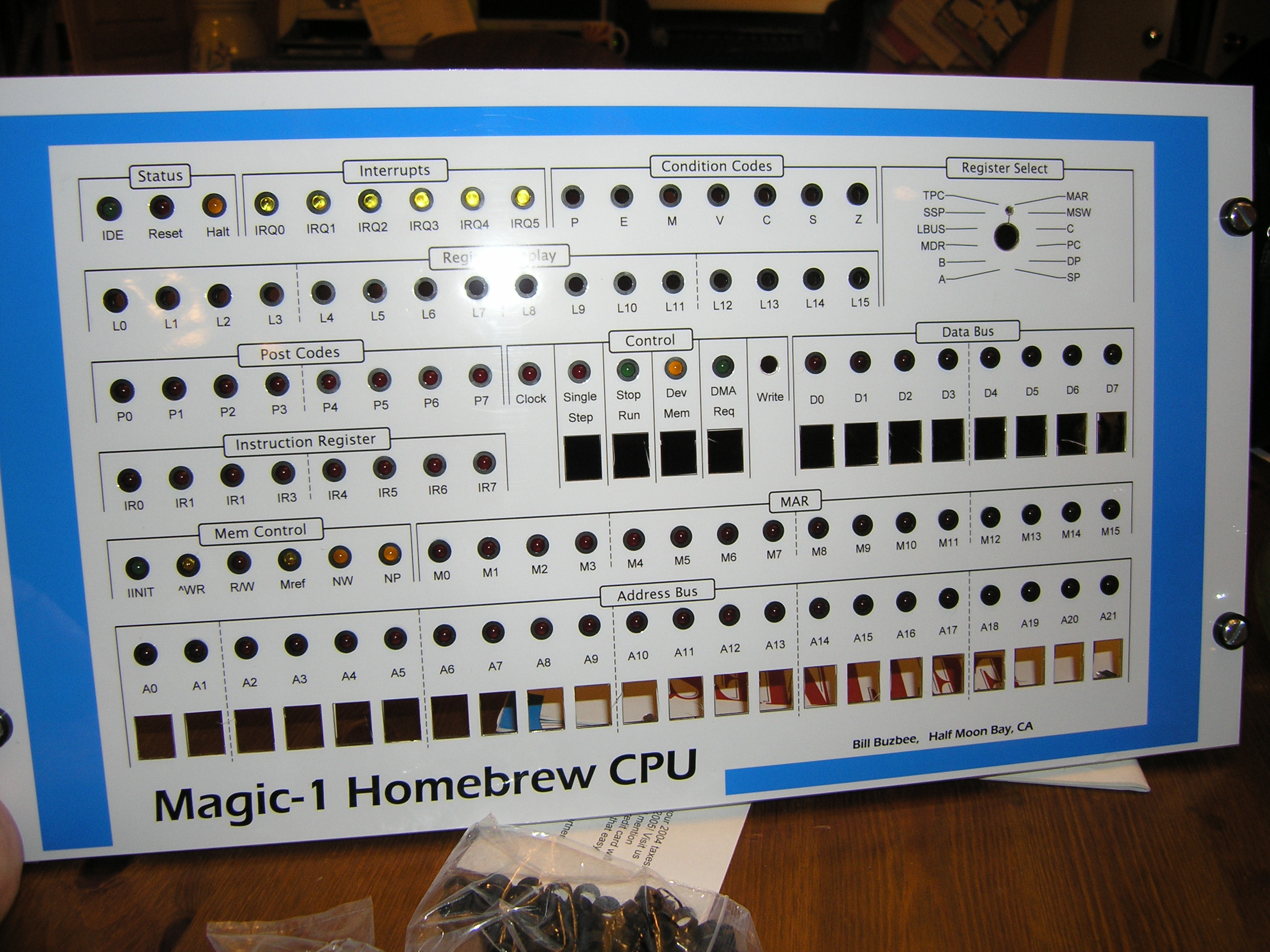
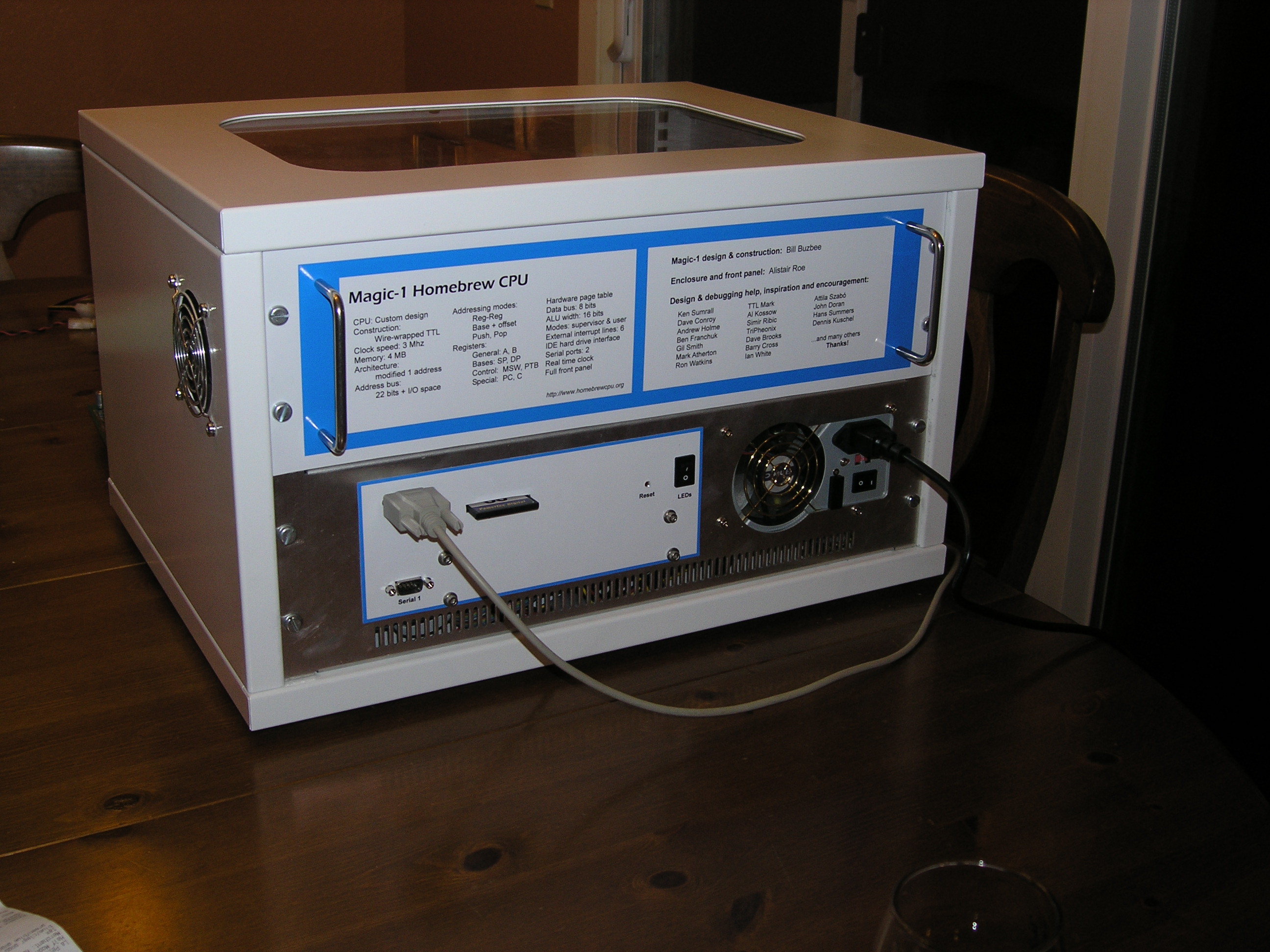
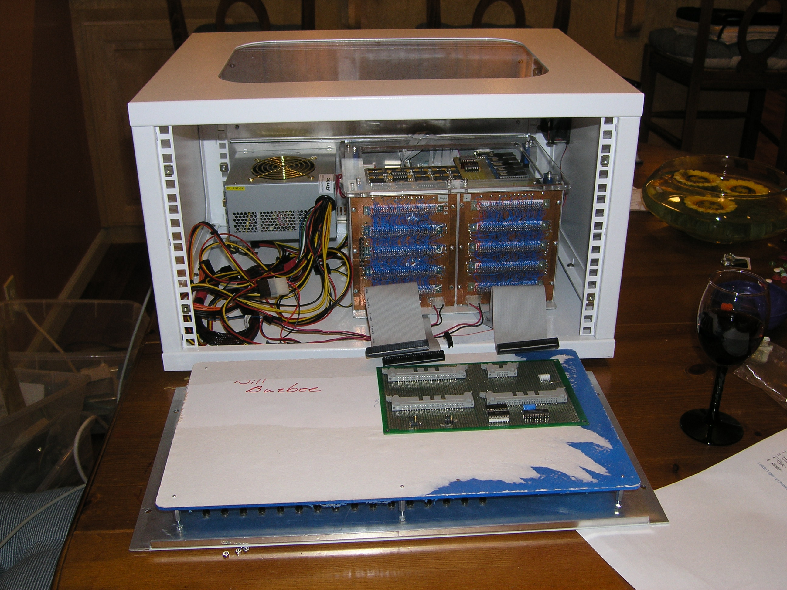
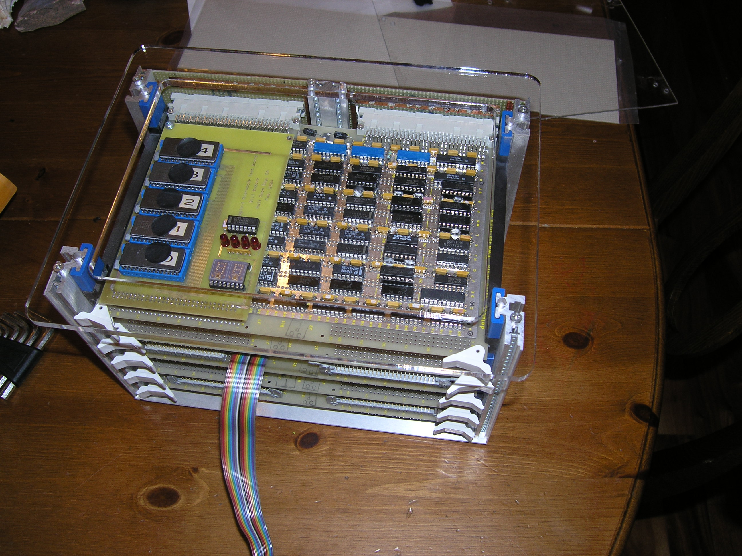
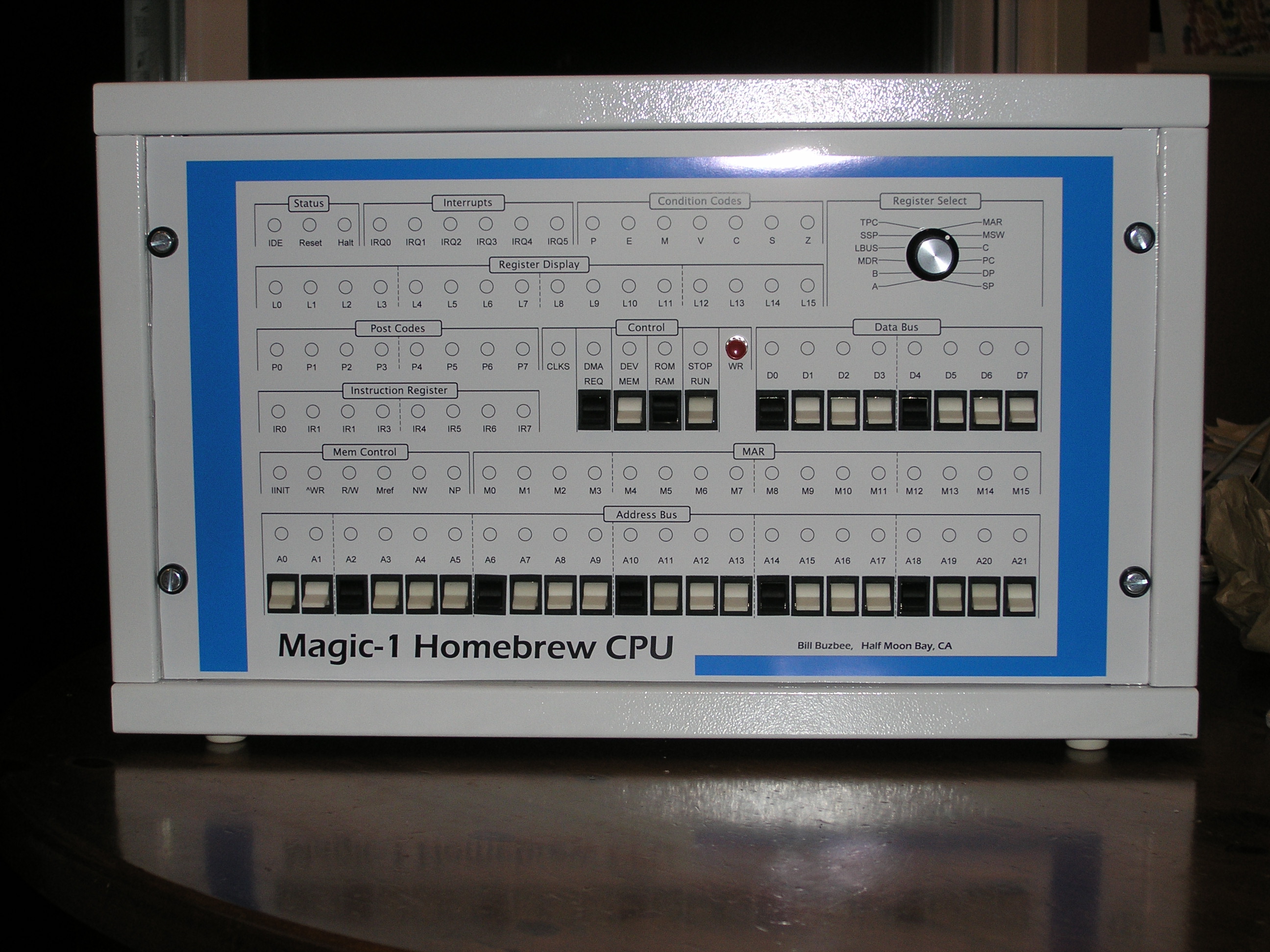
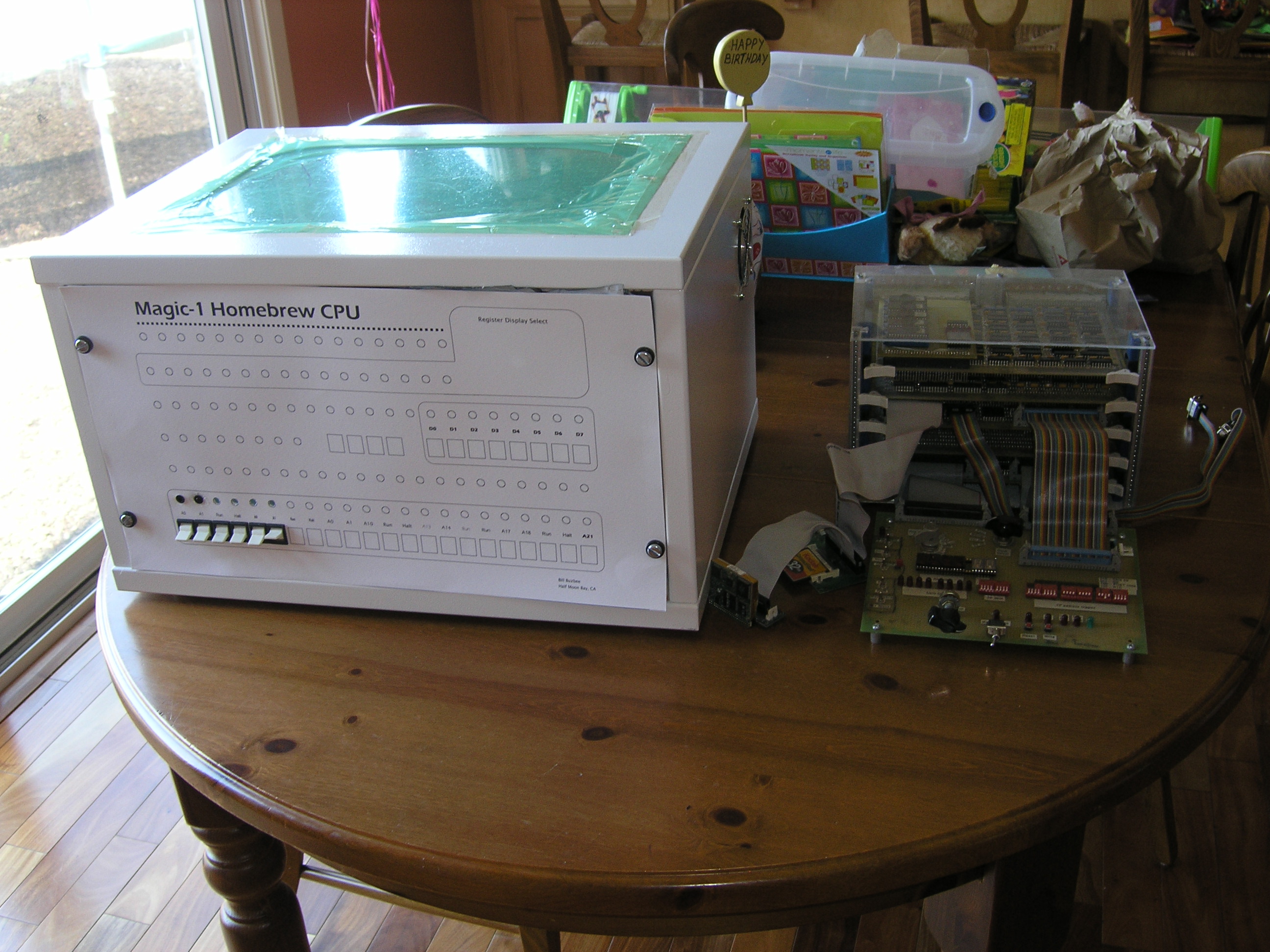
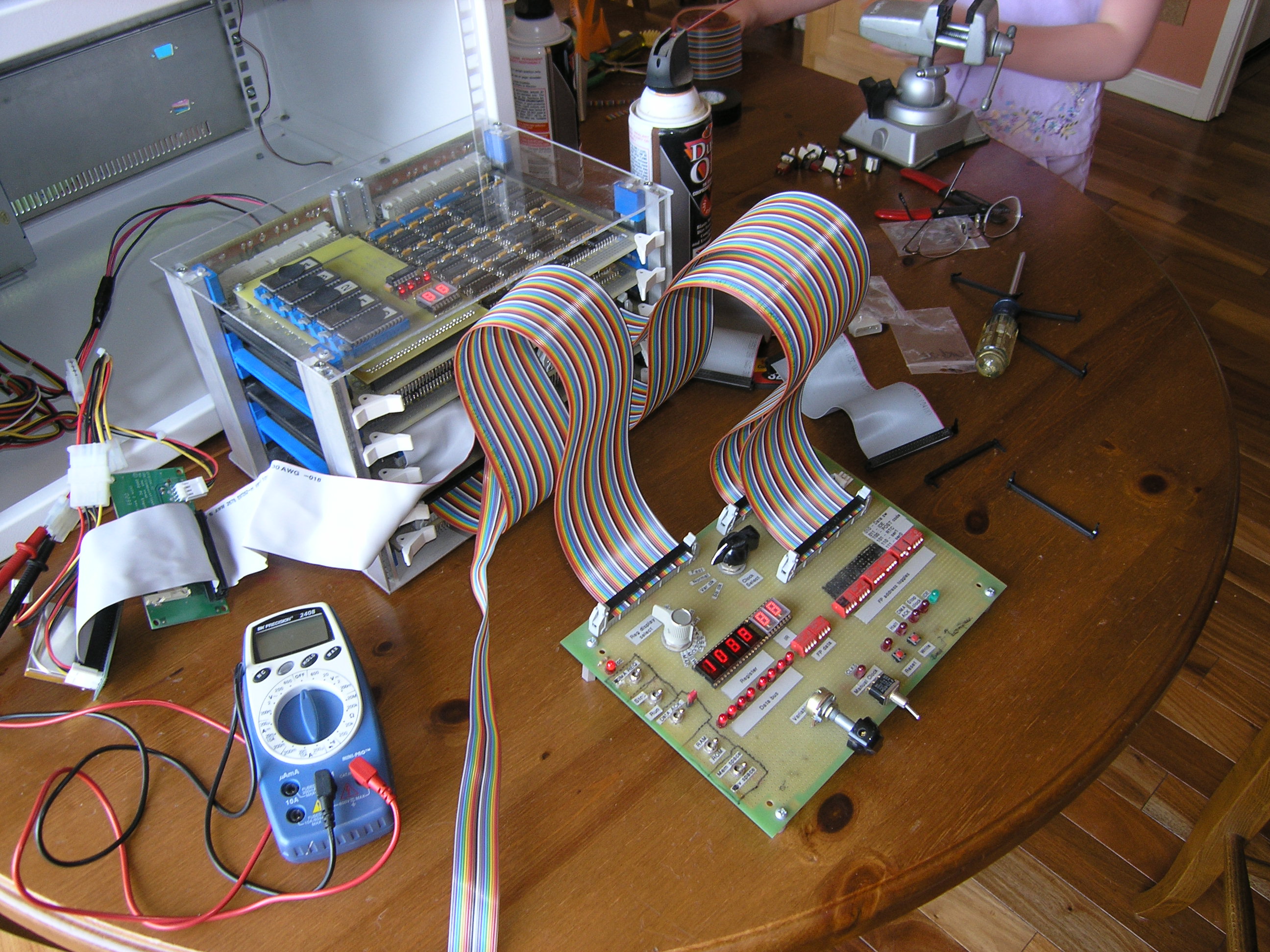
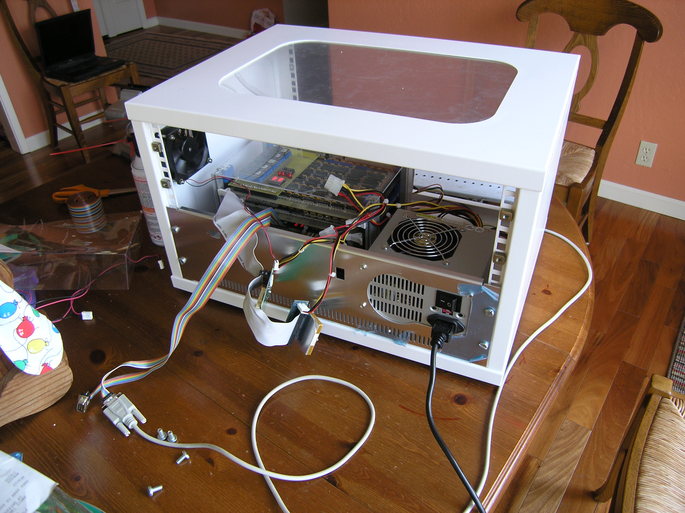
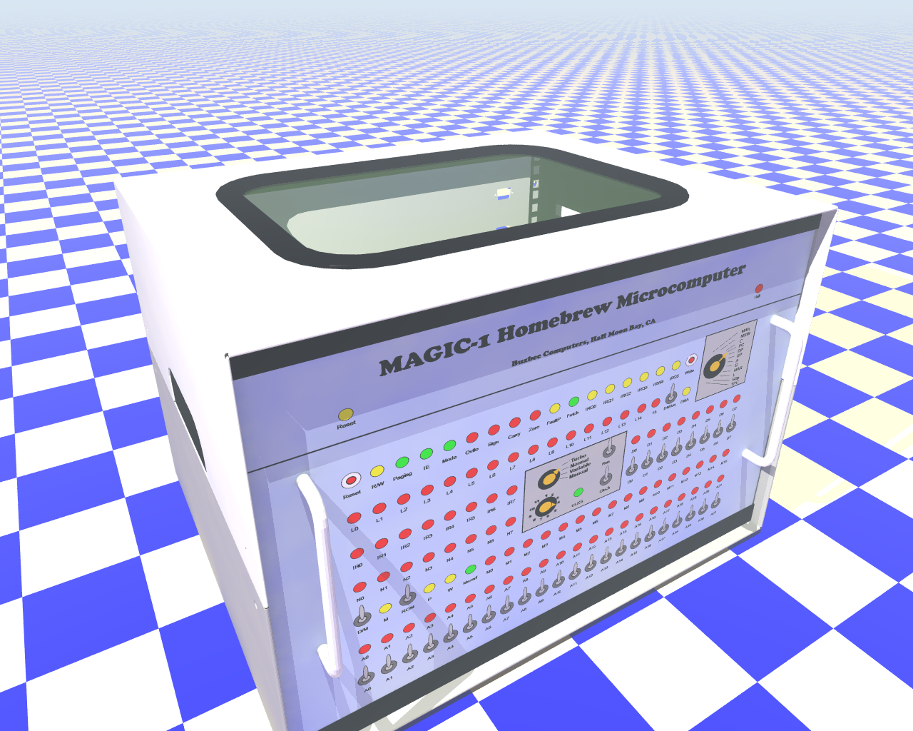
Front panel and enclosure construction [complete - 5/13/2005]5/13/2005It's done. Of course, I'm sure I'll find the occasional thing to tweak - and we're just talking about Magic-1's hardware. The software project ahead (particularly the Minix port) is going to take a lot of work and will probably take me a year or two. But still, I can say that Magic-1 is done. Hard to believe. I pretty much always have a hobby project or two working in the background, but Magic-1 has been a near (or maybe complete) obsession for the last four years. And, the damn thing really works - and works well. Anyway, enough of that. I've done a bit of tweaking since Mother's Day. First, Andrew Holme reminded me of the difficulties of doing pulldowns in TTL. I'm just going to let the IDE interrupt line float for now. When I get into the Minix port I'll enable that interrupt and the problem will go away. I spent some time working on the front panel LEDs. First, I decided to add a bit of color, and swapped out the interrupt enable, mode and paging enable LEDs with bi-color ones. So, for interrupt enable, green is enabled and red is disabled; for mode, green is user mode and red is supervisor mode and for paging green is paging enabled and red for paging disabled. I also did the same for the stop clock LED: green is running and red is stopped. The next thing I did was add an additional fan in the enclosure, with a power resistor to slow it down. The purpose of this fan is just to circulate air within the enclosure. Magic-1 wasn't getting hot by any means, but it was a little warmer than I thought ideal. With the second fan, you can barely detect any warmth on the boards (this is especially helped by the wire-wrap prototype boards themselves: the wire-wrap pins act as bunch of little heat sinks). After that, I started getting a little carried away. I added a fluorescent blue light bar to the inside top of the enclosure (along with a switch on the back panel to turn it on and off). It does nicely illuminate the inside of the enclosure, but I worry that it's the first step towards "pimping my ride." I'll resist the urge to add fuzzy dice and spinning rims. Finally, I noticed some problems with my LEDs. First, it appears that I was not paying attention when I bought my yellow LEDs from the surplus shop. They were not diffused, but rather were in a clear package. This caused them to be a bright point with poor field of view. I replaced them with diffused ones and they look much better. Secondly, with the large transparent window in the top of the case (as well as the case light), some of the lighter LEDs would appear to be illuminated because of the light coming from inside the case. To address this problem, I painted the back of every front panel LED with flat black paint. You can still see a little glow with the yellow LEDs, but in general the problem is solved. Not sure when I'll get the time, but soon I hope to reorganize this web site. I won't delete anything, but now that I'm no longer in design and construction mode it would make sense to have a summary page describing Magic-1, as well as some links to interesting pictures, text and movies (such as pointers to interesting diary entries, the video of the first successful Fibonacci run, etc). I've been adding junk to the site since 2001, and it's gotten pretty large and sprawling (and currently consumes 300 MB of storage. 5/8/2005Didn't do too much today (what with it being Mother's Day and all). However, since I did have the video camera out I went ahead and shot a quick video of Magic-1 running and uploaded it to the web site. As with most of my photography, it's of extremely poor quality. I'll try again later with better lighting. While doing the video, I noticed that IRQ1 was constantly being asserted. This is the interrupt request line that I've allocated to the IDE interface. I was a bit puzzled about what was going on there, as I am currently running with IDE interrupts disabled (using busy-wait loops for IO). A quick scan of the ATA spec, however, showed up a defect in my implementation. When IDE interrupts are disabled, the interface puts the IRQ line into a high-impendence state. I'm running it through an inverter, which would see this high-impedance state as an unconnected input. Since this is TTL, unconnected inputs tend to float to a HIGH logic state, which the inverter flips into Magic-1's low-active IRQ1. Just for kicks, I enabled IDE interrupts and they seemed to work fine (and the stuck IRQ1 disappeared). So, it looks like I need a pulldown resistor on that pin. Interestingly, I then referred back to Peter Faasse's 8255 IDE interface documentation (which I based Magic-1's interface on), and he does in fact have a 10K Ohm pulldown on this pin. Guess I just missed that earlier. Back to the enclosure and front panel, what I thought was a problem with POST code display was in fact pilot error. The POST code display works just fine. To add extra blinkiness, I modified the heartbeat interrupt code to increment the POST display once a second once we got past boot. I can't yet call the front panel and enclosure work complete. Still to go is bolting the card cage down. My issue here is that if I bolt it directly to the bottom of the enclosure, I won't be able to remove the lowest card. I have some thick nylon risers which would raise it up enough, but I'm pondering whether I should just go ahead and bolt it to the bottom. The reason is that even with the risers, it is quite difficult to remove the cards. I'm thinking about maybe just using an easily removed bolt or two on the assumption that I won't be pulling cards very often, and when I do I'll probably want to pull the cage anyway to get enough room to attach debugging probes. 5/7/2005We have blinky lights - and they look great. I completed the front panel wiring and after fixing a few mistakes Magic-1 fired up all bright and blinky:
I hope to take a video of it running and post it within the next couple of days. As might be expected, when running at full speed most of the LEDs are just slightly dimmed red. However, the operation of the heartbeat interrupt and clock bookkeeping gives off a nice regular blinky pattern. You get the full effect of the LEDs when running using the slow clock. There may be a problem with the post code display, but it also might just be pilot error. I'll write a test program soon to verify. Other than that, everything seems to work just fine. Very, very cool. Thanks again to Alistair for his fantastic front panel and enclosure - they really make Magic-1 complete. I'll do a full set of photos later (ideally during the day when I can avoid using my flash). Anyway, here are a couple of shots of the front panel. First, here it is with the wiring completed, but the protective plastic still in place.
Here's what it looks like all folded with the shield in place:
5/6/2005Slow and difficult - I really don't like dealing with long wires. Anyway, I'm about half-way done now.
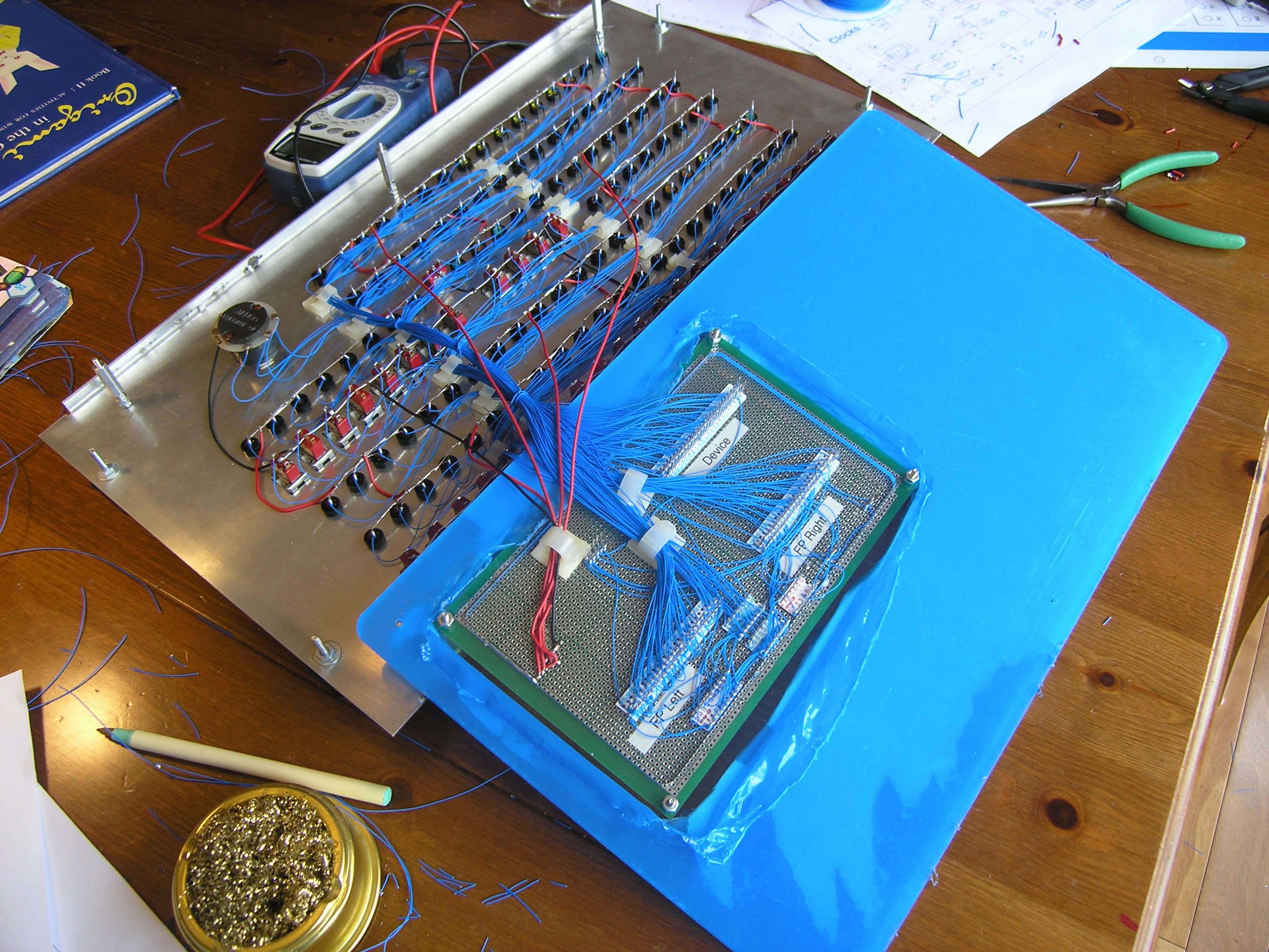
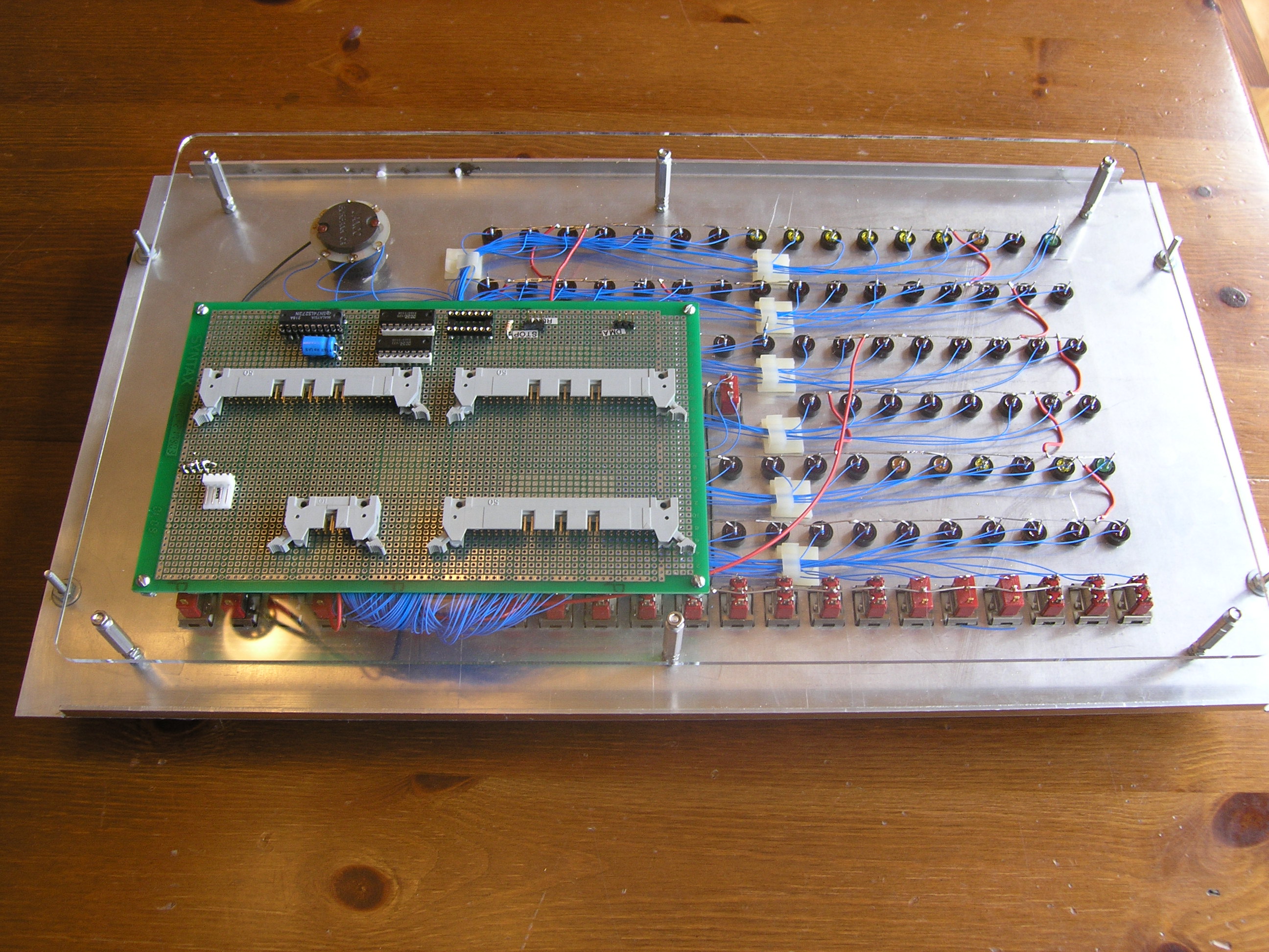
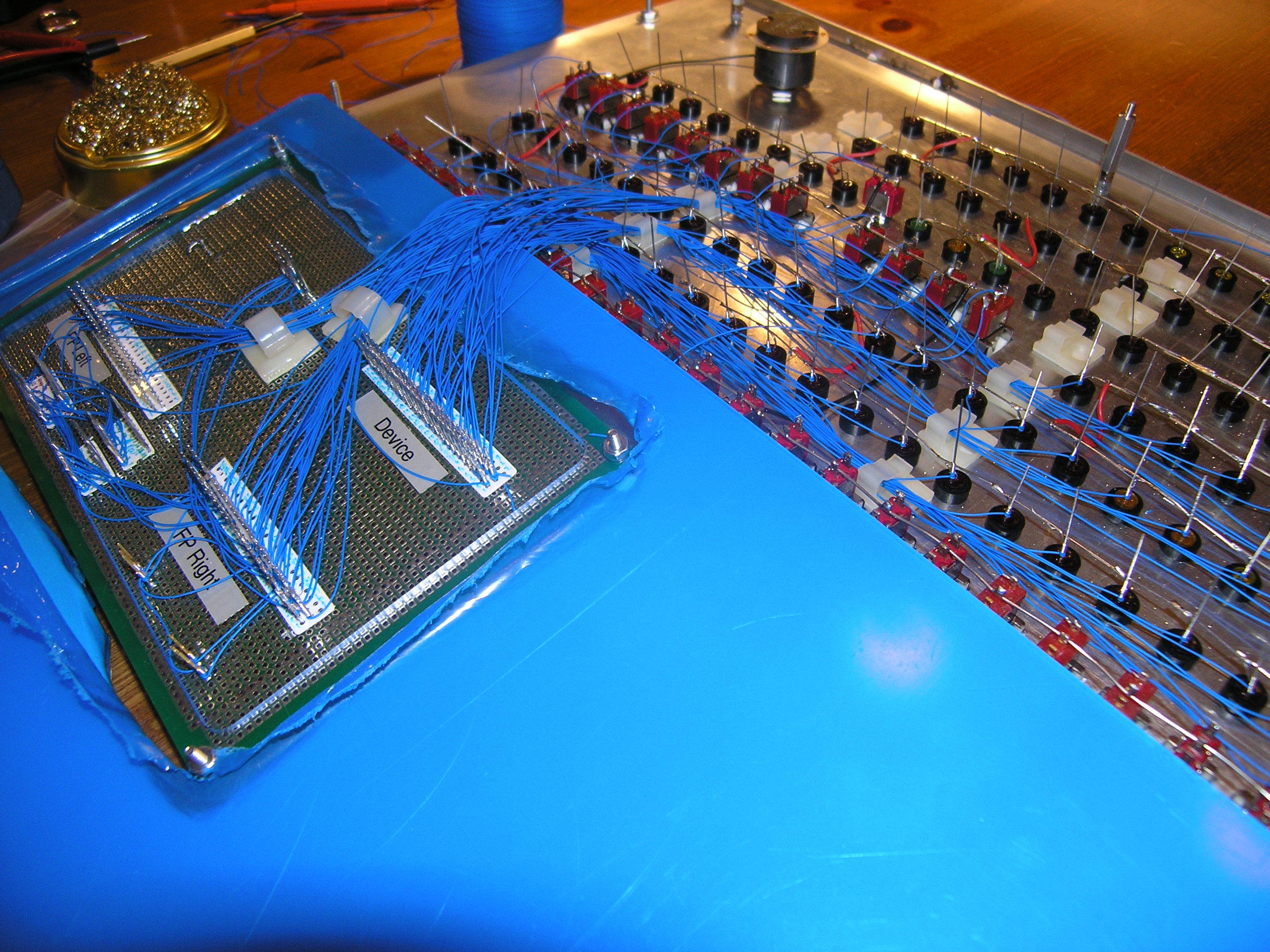
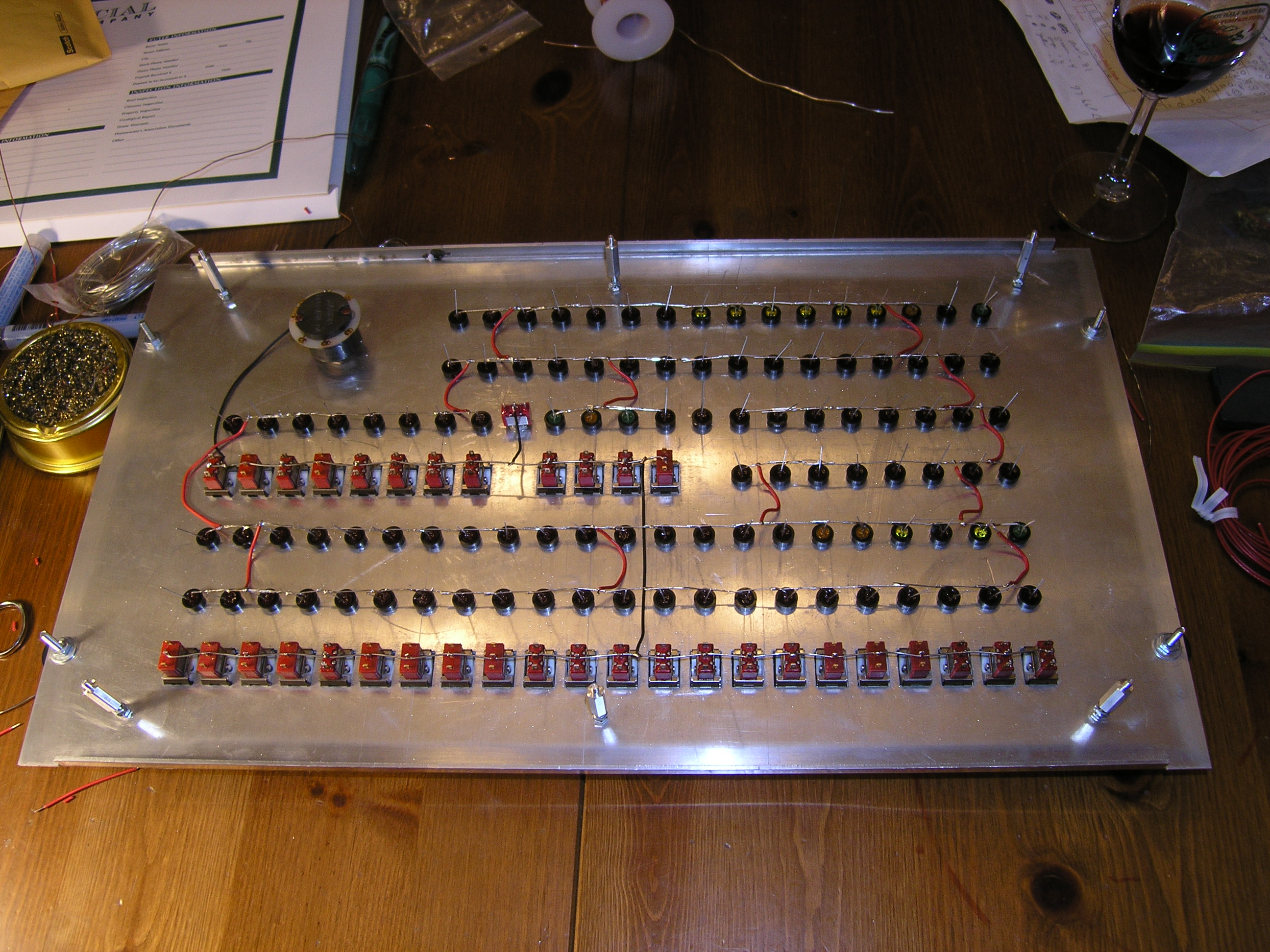
5/5/2005 [evening]Started the wiring tonight - and it's slow going. It will probably take a couple of work sessions to finish. So far, I've got all of the address bus switches and LEDs:
I'm going to complete the wiring before I reassemble Magic-1 (though I will individually test every LED and switch before removing the protective blue plastic from the FP shield and mount it to the front panel. Barring anything really unexpected, I'm on target to complete sometime this weekend. 5/5/2005 [morning]I realized this morning that if I needed any additional trimming done by Tap Plastics on the front panel shield, I would need to get it in today to be ready by this weekend. So, I annoyed the family early this morning by doing a free-hand cut (on the kitchen counter) of the new fan plate using the router bit of my Dremel tool on a scrap of acrylic. It was loud and ragged, but it seems to work out just fine in the original fan position:
You can see the air filter on the inside left of the enclosure, held to the new fan plate with a couple of Maia's elastic hair bands. I'm running the fan at full speed now in order to ensure positive air pressure on the inside of the enclosure. I believe it will be enough, as the power supply's exhaust fans barely spin at Magic-1's low power load. It is a bit noisier than before, but it's good enough. I will do some minor adjustments later - in particular cleaning up and slightly widening the fan hole cutout on the plate. 5/4/2005All of the LEDs and switches are now mounted in the front panel, and the common power (for the LEDs) and common ground (for the switches) are wired up.
It's getting pretty close to done. The final wiring session will involve running a single wire to each of the LEDs and switches and connecting them to the proper pin on the socket card. That's going to be a little tricky. I want to keep it neat, and route the wires in little bundles (held together by some wire clips I've got) without too much slack. This strikes me as a job I want to do in one sitting (with a couple of breaks). That probably means I'll need to put it off until this weekend. Meanwhile, the new back labels are back from Kinko's, laminated and looking good. Thursday and Friday I'll install those and decide what I'm going to do with the air filter. I can't wait to see what Magic-1 is going to look like all blinky. 5/3/2005 [evening]The big event of the evening was my two girls' school presentation of Cinderella. Elizabeth (13) played the steward and Maia (7) was a mouse. Putting aside any hint of parental favoritism, I can state as an absolute objective fact that never in the history of theatre has there been a finer steward than Elizabeth, nor a mouse portrayed with such endearing cuteness as Maia. After getting them all calmed down, cleaned up and off to bed I spent a few minutes on Magic-1 to unwind. First, I tried a few configurations of filter and fan and mostly convinced myself that I have two workable solutions. One is to use a thinner filter (which I have) and move the card up against the power supply. That would open up just enough room to add the filter to the fan's current location. The benefit is that the filtered air flow would be directed right at the card cage. The down side is that it's a really, really tight fit. The other option is the one I started with - swapping the side panels and putting the fan/filter combo in the front left. The clearance problem I ran into this morning was the edge of the front panel acrylic shield. The solution is to cut away a chunk of the shield. The benefit is that I'd have plenty of room and wouldn't have to crowd my card cage. The down side is that I'd have to take the shield back to Tap for adjustment. I'm not sure which way I'll go. My plan is to go ahead and cut the filter plate myself out of some scrap acrylic that I have and just see how things look. After that, I sat down at the kitchen table with a glass of wine and the front panels and started fitting the LEDs. Here's how it ended:
... and a front view:
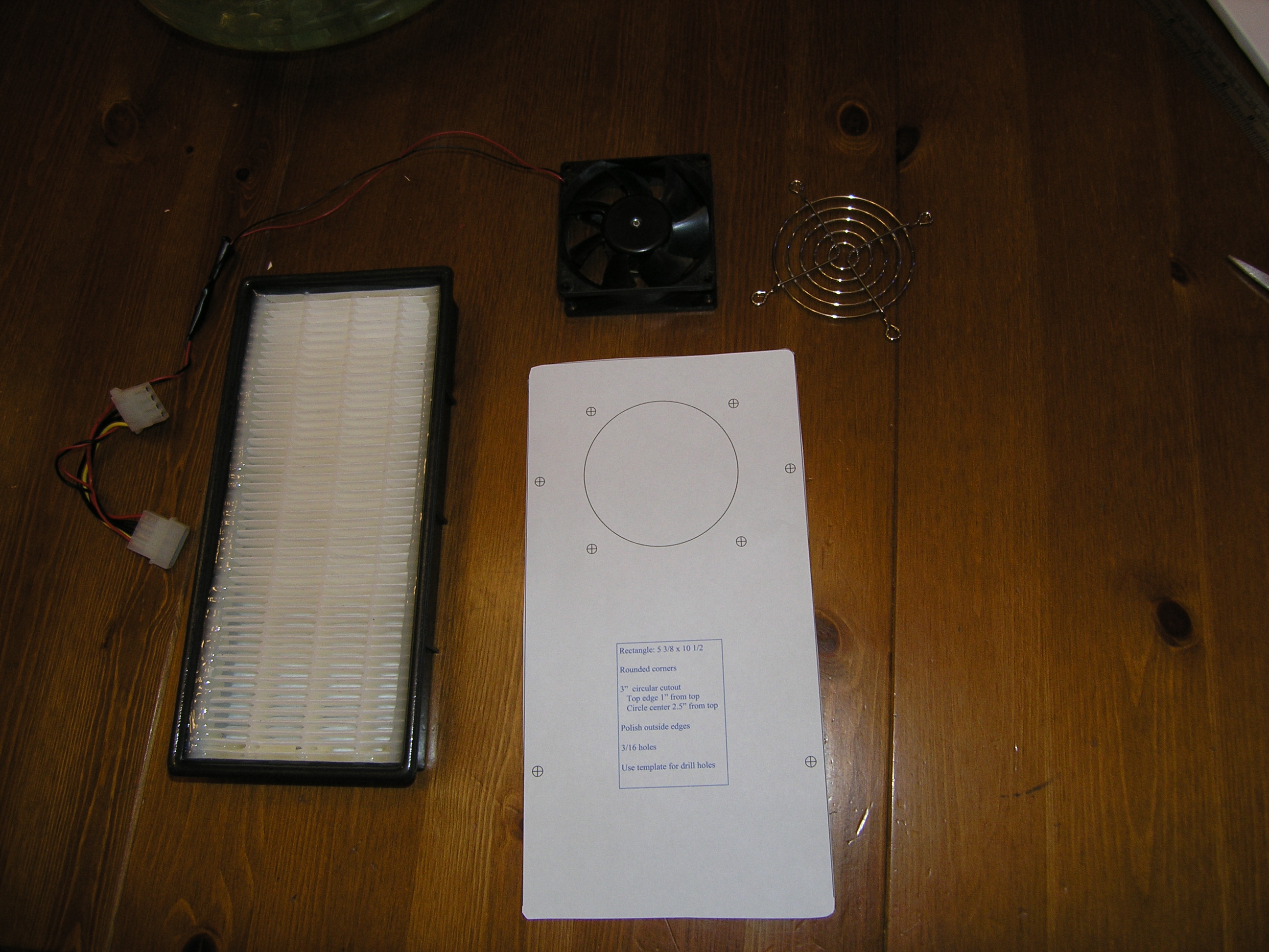
I would have finished, but ran out of red LEDs. My favorite electronics part store is Anchor Electronics, but I have to remember that when they sells bulk parts by the bag "100" doesn't actually mean 100, but should be read as "a bunch", or "all we could fit in a bag this size". Anyway, I'll pick up enough to finish tomorrow and with luck, will start connecting all of the power leads to the bare bus wire. 5/3/2005 [morning]Oops - did a test fit of my filter plate template and find that I've got some clearance problems. Need to think about this some more. 5/2/2005A bit tired tonight, so I decided not to start putting in LEDs. Instead, I worked on the air filter scheme. I found a nice HEPA filter at the hardware store that was meant for a small home air purifier. Next, I created a template for the plate which will hold the filter against the fan:
The grill will go on the outside of the enclosure and the fan immediately inside - just as it does today. However, the filter plate will be bolted to the fan. I'll then just strap the filter against the plate and hold it down with clips of some sort (using the 4 outside holes on the filter plate). The filter already has a nice raised rubberized gasket all along the front edge. That will give it good air distribution to the full filter surface and also seal nicely. I'll probably have Tap Plastics cut it for me. The other thing I did tonight was print off a new set of back panel artwork. I decided to fill the large space on the lower panel with a key to describe the DIP switch setting for clock source select. The new top label includes a tip 'o the hat to Merlin Skinner for his air filter suggestion. 5/1/2005I don't mind making mistakes so much, but I really hate making the same ones over and over again. The problem with the front panel socket card was one of orientation. When I set up the wire-wrap tag for the 10-wire ribbon that goes to the back panel IDE drive platform I got it mirror-image wrong. Anyway, fairly quick fix and Magic-1 was up and running. It's currently running completely in the new enclosure and the old temporary front panel card is officially in retirement. I went ahead and put it back online, so it should be available for telnet sessions at least until tomorrow night - when I hope to start installing LEDs. The general build plan for the front panel is to first install all of the LEDs in the front panel. Then, I'll bend one lead (the right one, I hope) of all of the LEDs in a right angle and connect them together using solder to a series of bare bus wires. These will eventually be connected to the special LED power feed. After that, I'll start the individual LED wiring - wrapping each remaining lead and connecting it to the appropriate pin on the front panel socket card. Oh, I have decided to have 2 of the LEDs use the main power supply, so they will always be active - CLKS and IDE drive activity indicator. The reason for doing all of the LEDs first is that they won't disturb the flat front surface of the panel, making wiring easier. Next up, I'll wire in all of the switches, and then disable the temporary jumpers on the socket card. Not sure how long all this will take. I'm inclined to say a couple of weeks, but chances are once I start getting close I'll push through to the finish. 4/30/2005Well, the wife's party came and went Friday. I survived. Anyway, got back to Magic-1 today and made a fair amount of progress. I completed the wiring on the front panel socket card - except for those wires actually going to the front panel (which will be the bulk of them). On the card is some logic to capture the post code value (I didn't have room to bring it out directly on the ribbon cables). Also, there's some wiring to the socket that connects the rear panel switches. Here's the kitchen table aftermath:
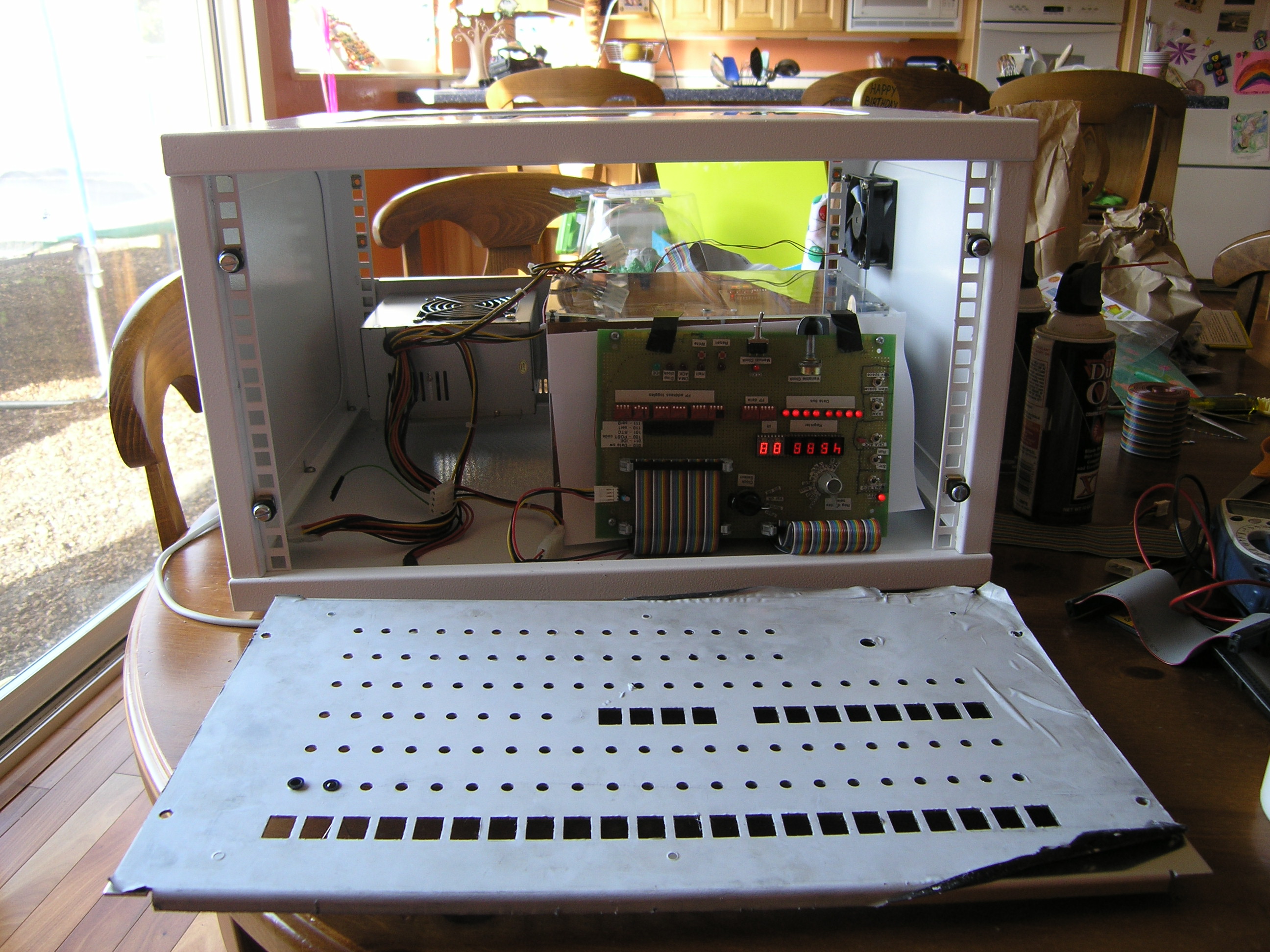
There are a few front panel switches that must be working for the machine to run, so I also put a couple of jumpers on the card. The plan is to get Magic-1 running with the new card now, and then over a few sessions add the LEDs and switches to the front panel and wire them up to the socket card. I get a bit nervous every time I do significant physical manipulation of Magic-1. It's been rock-solid for months now, but there are so many wires to pull, jostle or break I'm trying to keep stress to a minimum. Anyway, I put Magic-1 back together inside of the enclosure with the new back panel, power supply and front panel socket card instead of the old temporary front panel. Unfortunately, when I applied power things did not go perfectly. M-1 appeared to be stuck in a DMA request loop (looping on microcode address 0x07). The good news is that when I replaced the new socket card with the old temporary front panel Magic-1 came back to life and ran through it's paces perfectly. So, I've got a bit of debugging to do on the new card. I'll work on that tomorrow. Also today I modified the top rear panel a bit. I think I will be removing this panel fairly regularly and doing so was a bit difficult. So, on Friday I swung by one of the Silicon Valley surplus electronics shops (HSC) and picked up a couple of cheap simple handles. Here's what it looks like now from the rear:
Here's a front view showing how the socket card will work, attached to the front panel with the acrylic shield:
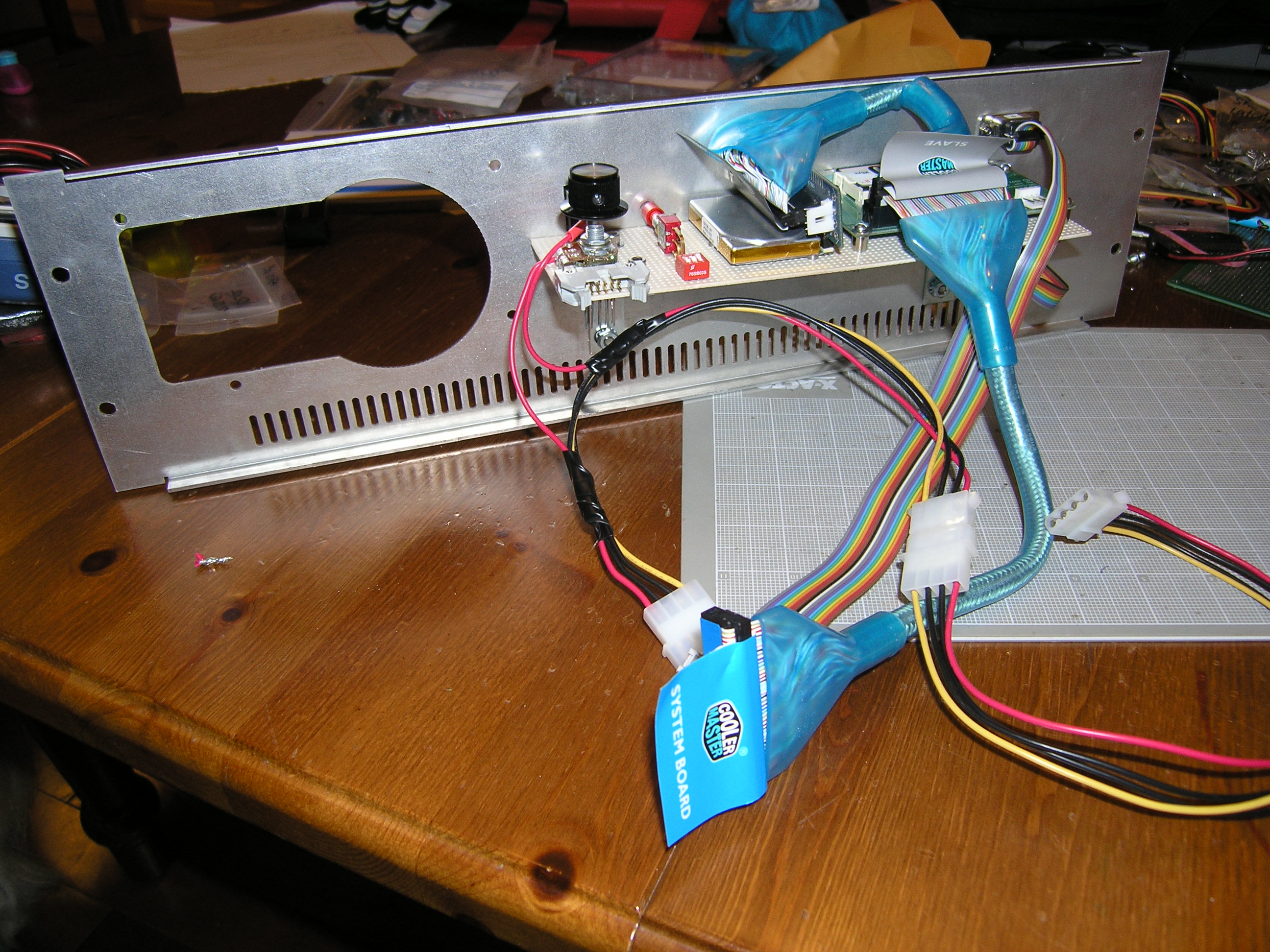
Also tonight I got a timely suggestion from Merlin Skinner. Merlin suggests that I might want to use a small automotive or motorcycle air filter to keep gunk from getting all over the inside of the case. As it turns out, I was worrying about this very problem earlier today. When I started putting things back together today I noticed that the acrylic top window had already accumulated a thin layer of dust. The general idea would be to have the muffin fan suck air into the case, forcing it through a small air filter on the inside of the case. As things stand now, this wouldn't work. There just isn't enough room between the muffin fan and the top edge of the card cage. However, I believe that the sides of the enclosure are symmetrical. If I swapped the left and right sides of the case, the fan would be repositioned to the upper left - right in front the large empty space currently filled with wads of useless power-supply cables. That would give me lots of room for an air filter that could keep all my clear acrylic dust-free. Anyway, interesting idea. I like it. Thanks Merlin! 4/25/2005Finished wiring the lower back panel. I spliced in a power connector to the switch on the back. That will allow me to give the front panel LEDs their own separate power supply (which I can turn off at night without shutting the machine down). I also snipped the serial cable that comes off of the device card in half and attached a couple of connectors. This will allow me to completely remove the back panel without having to remove any cards. Finally, I bought a colorful IDE cable. I'm not sure I'm going to keep it, though. It was billed as flexible, but is isn't very flexible between the master and slave connectors. It works, but puts a bit more stress on my drives than I'd like.
Here's a shot from the outside:
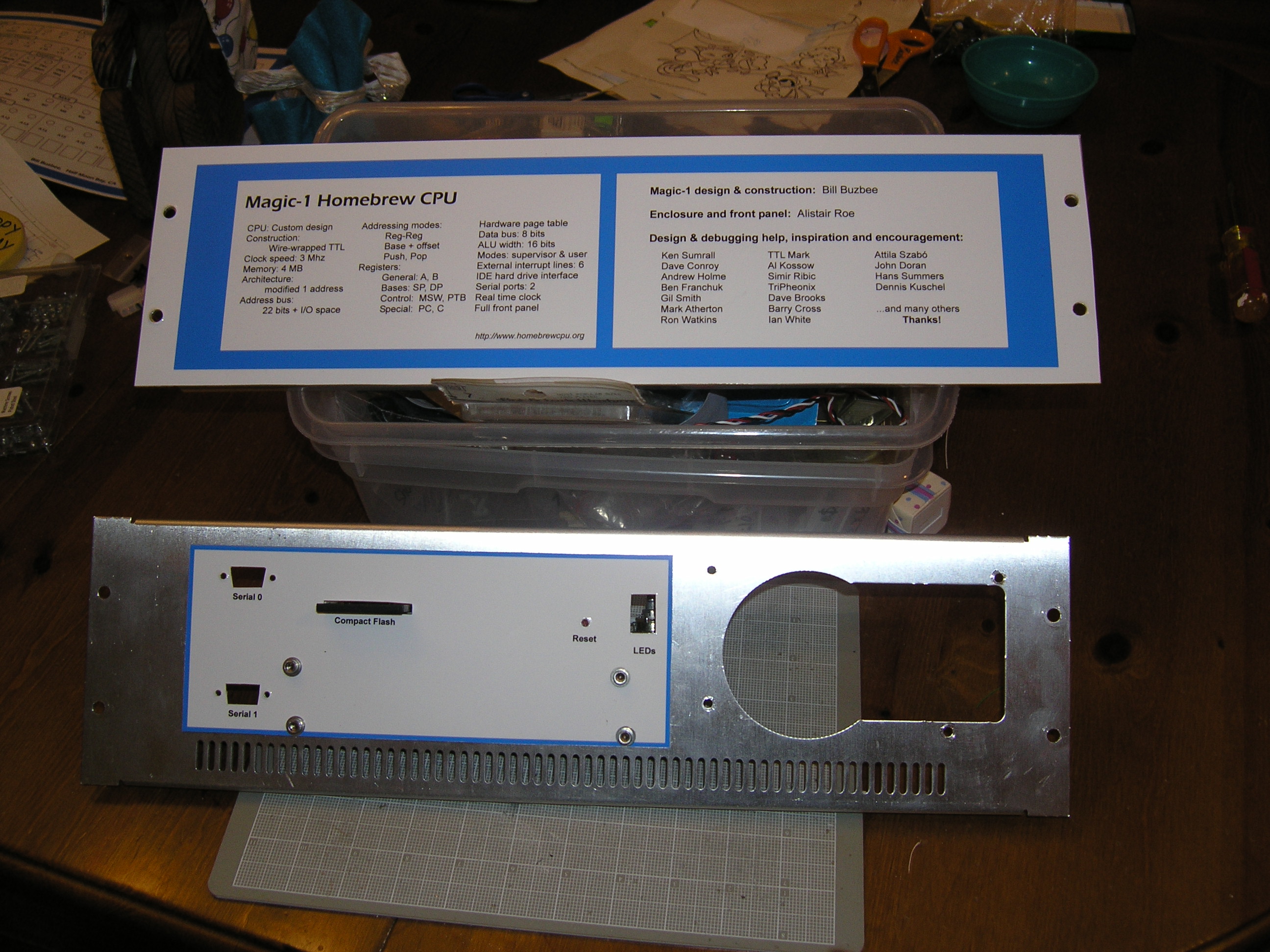
I had planned on starting the front panel socket card tonight, but when I placed the sockets I realized that my new sockets don't work very well with the current cables. I could easily fix things by putting new connectors on the ribbons rotated 180 degrees, but then the cables wouldn't be compatible with the old temporary front panel. The problem is that the sockets I bought were the 90 degree kind, and my intent was to have the opening facing down. I did this thinking it might save a tiny amount of space. However, if I get regular sockets my cables will work as-is. I'll probably go with regular sockets. 4/24/2005While finishing up the IDE platform, I had an idea about back panel artwork. The back panel consists of a pair of 3U covers. The bottom one has nice venting, power supply and 2 db9 holes. I decided it wasn't reasonable to try to cover the entire thing like I did the front panel, because matching all of the cutouts would be too difficult. Instead, I just decided to use a simple bordered rectangle covering the switches. However, the top 3U panel currently has no cutouts - and could easily be covered. So, my idea was to put a little identifying info on the top rear panel: clock speed, memory size, etc. More importantly, though, was that this would give me a chance to name some of the many folks who have helped me out along the way. I printed the panels and was able to use my wife's laminating machine because it could handle up to 9" wide sheets. Here's how it ended up:
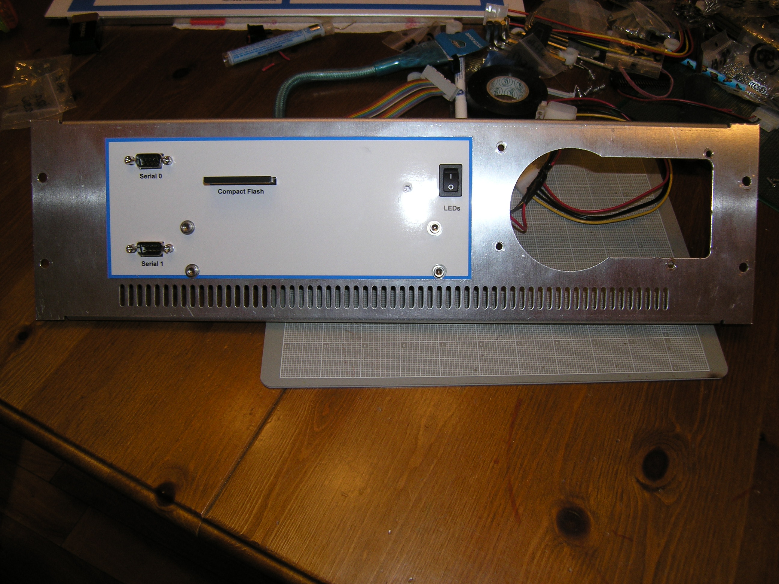
Note also that I cut some new holes in the back panel: the compact flash shot, the mounting holes and a reset pin hole. I was particularly pleased with how the CF slot came out. That one took me quite a while. My target slot heights was exactly the size of my nibbler. So, to make it I drilled a smaller hole and then slowly and carefully widened it with some tiny files until the nibbler could fit in and finish the job. Here's what the platform looks like in place:
For reference, pin assignment of the platform header:
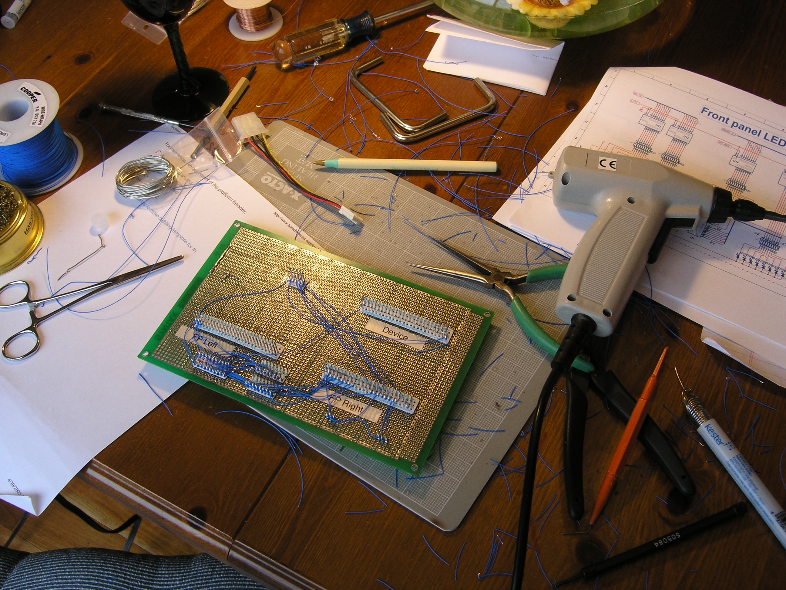
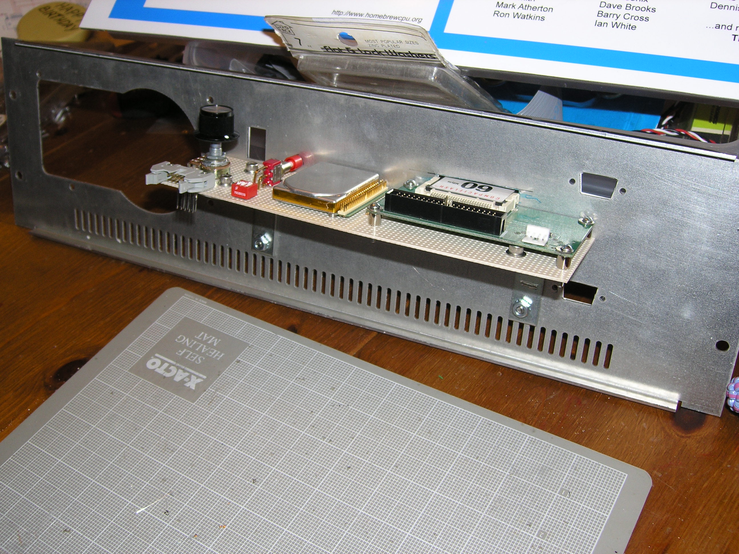
I didn't get a chance to make a drilling template for the card cage. Perhaps tomorrow. 4/23/2005Lots of progress in the garage (filled the van with garbage and took it to the dump). Lots of progress in the back yard (repaired long-broken sprinkler system). Lots of progress cleaning the house (and doing laundry). Little progress on Magic-1. I did sneak a few minutes and built up a couple of small items. First, I put together a couple of 30 Ohm power resisters with a standard PC power socket. I'll use this to give me the 800 ma 12 volt minimum current required by my switching power supply. Second, I drilled a few of the holes I needed in the perf board and mounted the brackets, both IDE drives and the switches. I still have to do a bit of wiring (mostly bringing the switches to the 10-pin ribbon cable socket).
The bracket side will be mounted flush against the lower back panel. I'll cut a slot to allow insertion of a compact flash card, and will also put a pencil-sized hole at the position of the red push button. That's RESET, and it will be recessed to avoid accidents. I hope to put together a set of hole templates tomorrow (back panel, and mounting holes for the power resistors and card cage on the bottom of the enclosure). If I can get those, I'll stop by a friend's house after work tomorrow and use his drill press. 4/22/2005Picked up the other main acrylic piece from Tap Plastics today. It's the new top for the card cage, with the center cut out to allow me to swap microcode EPROMs without removing the control card. I think it looks really nice:
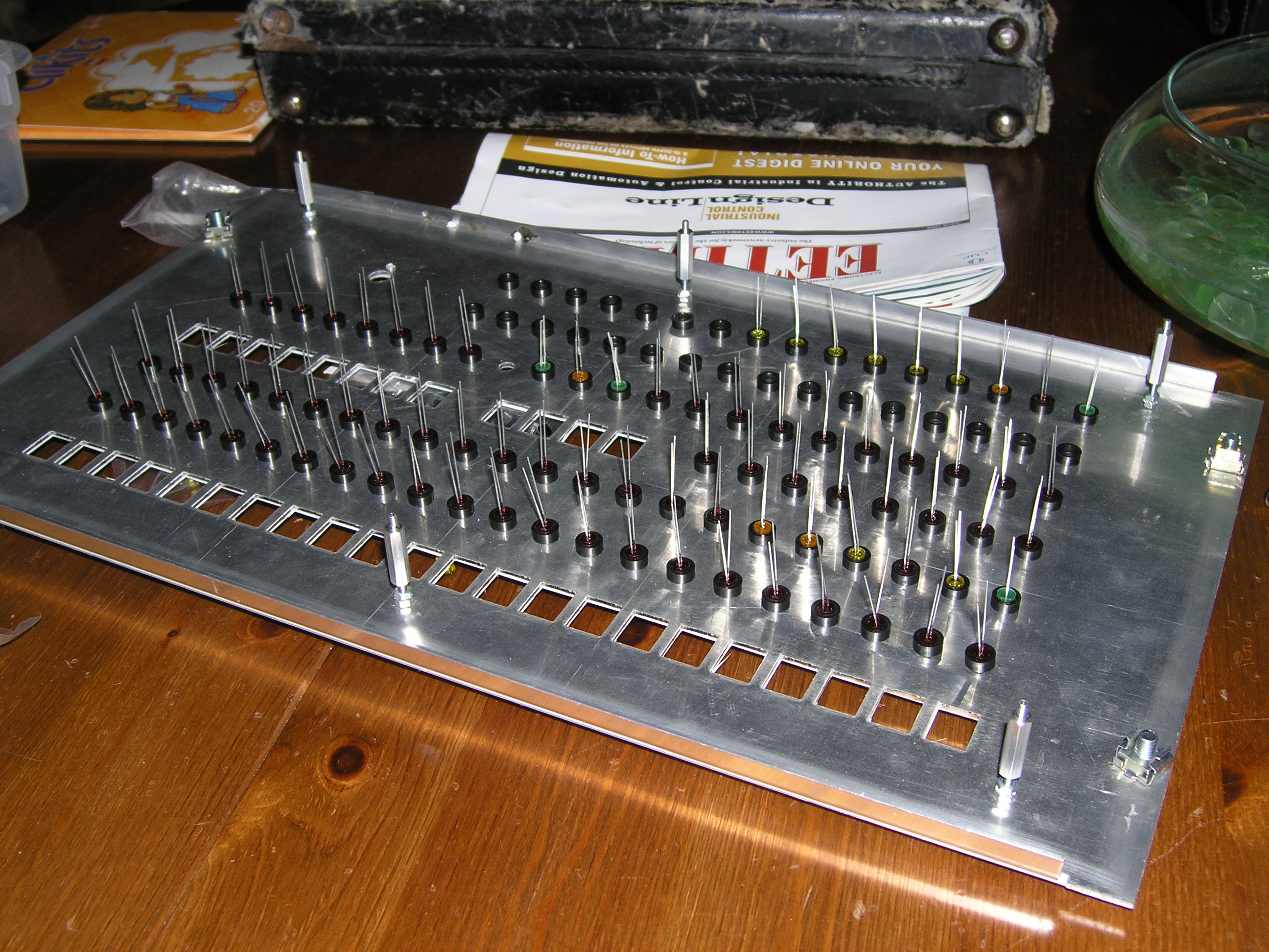
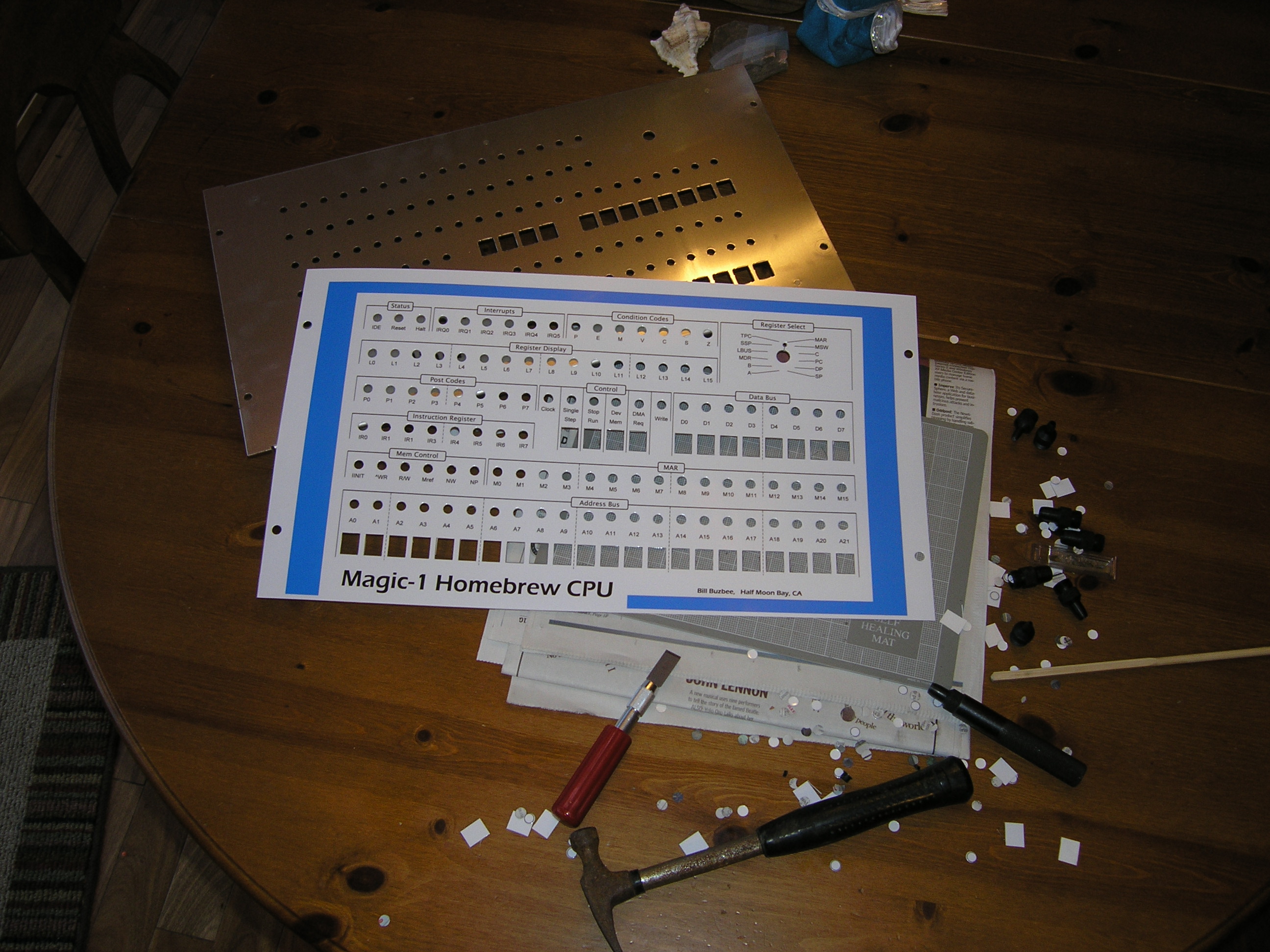
I only had a few minutes to play between chores, but I did manage to cut a new platform for the IDE drives out of perfboard. The first was a bit crowded. Also, I have two IDE <-> compact flash adapters. The first one I tried took up less space, but I realized that the CF card wouldn't stick out of the slot I'm going to cut in the lower back cover very far at all (and would make it really difficult to pull the card out). The other adapter will allow me to have up to a half-inch or so of the card sticking out, but it takes up more floor space. Anyway, I've decided to use the latter (with about a 1/4 inch of the card sticking out). Also, since I've got more place to play with, I'm experimenting with mounting the HP Kittyhawk drive flat rather than on its side. With luck, I'll find the time to drill mounting holes in the perfboard tomorrow and do a mock-up. Once that's done, I'll use the nibbler to cut the CF slot. The slot will be the anchor for the rest of the mounting holes (and the access hole for the reset switch). 4/21/2005It's looking good - really good. The front panel artwork came back from the laminator today, along with the first of the acrylic pieces. I used 5 mil glossy lamination (both sides, done at Kinko's). It only took a hour or so with my 7 mm circle hole punch and .5" square Xacto blade to cut out all of the holes. Made a nice mess, but worked really well. The circle punch was especially useful - it would have been a nightmare to try to cut all of those circles with a blade.
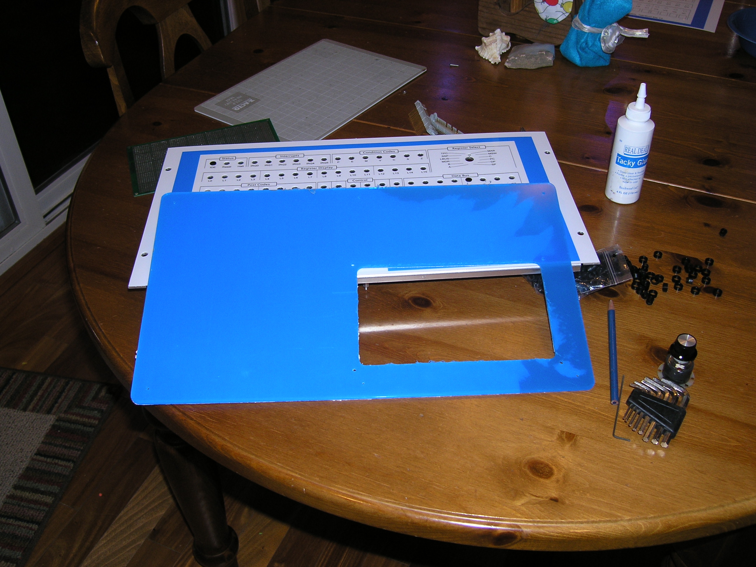
The only mishap of the night came when I drilled the tiny hole near the register select switch. The hole is for the tab of a slotted washer that keeps the rotary switch from slipping with use. I'd taken great care in precisely locating the hole (7.5 degrees offset from 12-noon position). Sadly, I thought I could drill it out using my hand-held electric drill. Naturally, the drill bit walked and the hole ended up in the wrong spot. I have to get myself a drill press one of these days. Anyway, I managed to correct my error with a bit of work with a tiny file. I installed the switch for testing and it is aligned just right. Next up was attaching the artwork to the front panel. I smeared the back side (mostly just the edges) of the artwork with tacky glue. I then slapped it on and put in the LED clips to align everything and hold it down while it dries. In truth, I probably could have gotten away without glue - the lamination makes it pretty stiff and all of the LEDs and switches will hold things down. Here's a picture of the shield. It's actually clear acrylic, but I'm keeping the protective covers as long as I can.
Here's how it is going to work:
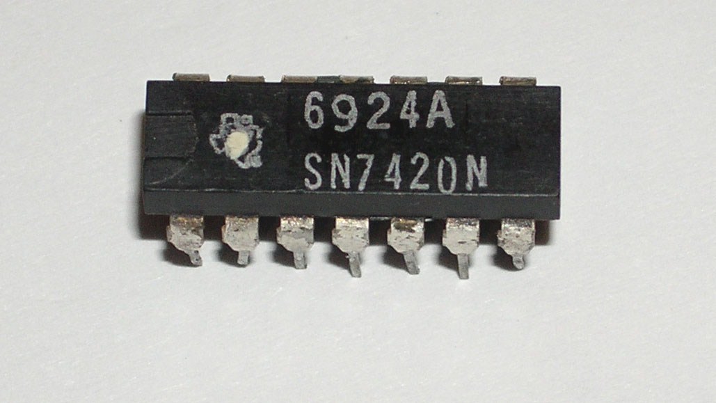
Unfortunately, it looks like I'm going to have a very busy weekend. My wife is throwing a party of sorts next Friday, which means lots of house cleaning and the long list of household repairs I've been ignoring for months. If I do find some time, my focus will be on the platform that will hold the IDE drives and clock control switches. After that, it will be time to drill the card cage mounting holes. After tonight's experience, I'll definitely be borrowing a drill press to do those. 4/20/2005Another very cool addition to Magic-1 arrived today from Alistair Roe - a 7420 with a date code indicating it was manufactured in week 24 of 1969. I'll be adding this device when I reassemble Magic-1 this weekend. I very much like the idea of Magic-1 using a 36-year-old logic element. As Alistair pointed out, this chip was manufactured a month before the Apollo 11 moon landing and about 4 months before the first ever ARPANET message was sent. Soon, it will be playing a key role in Magic-1's processing abilities. Here's a picture:
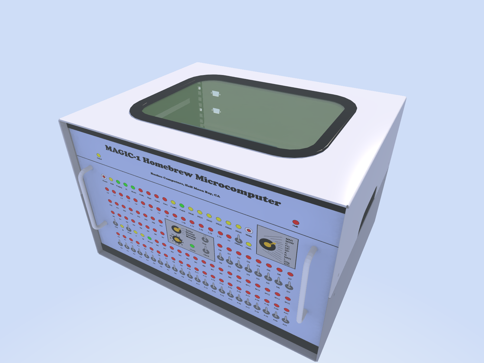
Things are progressing nicely on the front panel and enclosure front. I printed out the final front panel art this morning and sent it off to the copy shop to be laminated. Here's what it will look like:
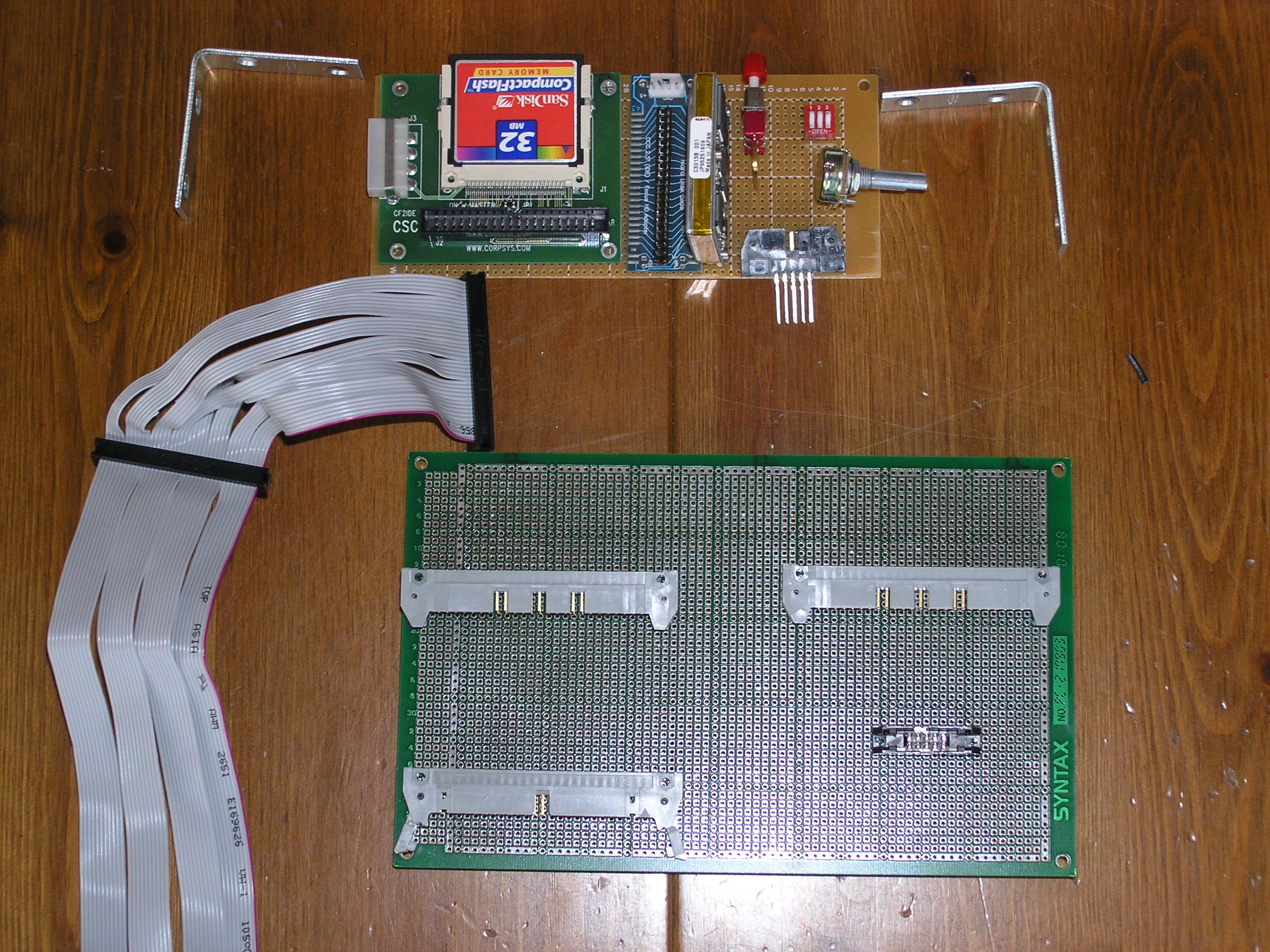
I'm also a few custom Plexiglas parts made to help piece things together. With luck, I'll start wiring up switches and LEDs this weekend. 4/17/2005There wasn't enough room on the front panel for all of the switches that Magic-1 supports. Left off were the clock source select (which chooses between 2 crystals, 1 slow variable-speed clock and a single-step clock), the reset button and a switch that decides whether the 1st 16K bytes of physical address space are mapped to the boot ROM or just RAM. My first thought was to mount these on the rear panel. However, after thinking about it a bit I've decided to mount them on a perf-board inside of the enclosure accessible only by removing the top half o the back panel (except for the reset button). These switches won't be used much at all, and when I want to use them removing the top rear access panel won't be difficult (particularly if I can find some thumb screws of the right size). The other reason that decided me was that I needed to construct a platform to mount the IDE drives on anyway. I'm using a tiny HP Kittyhawk 1.3" hard drive and a compact flash card. I'll use a strip of perfboard to mount both hard drives, plus the switches. My plan is to cut a slot in the back panel so that I can swap flash cards without removing the panel, as well as hit the reset button. Today I cut down an old prototype card to size. Here's a picture with the parts laid out approximately how they'll go.
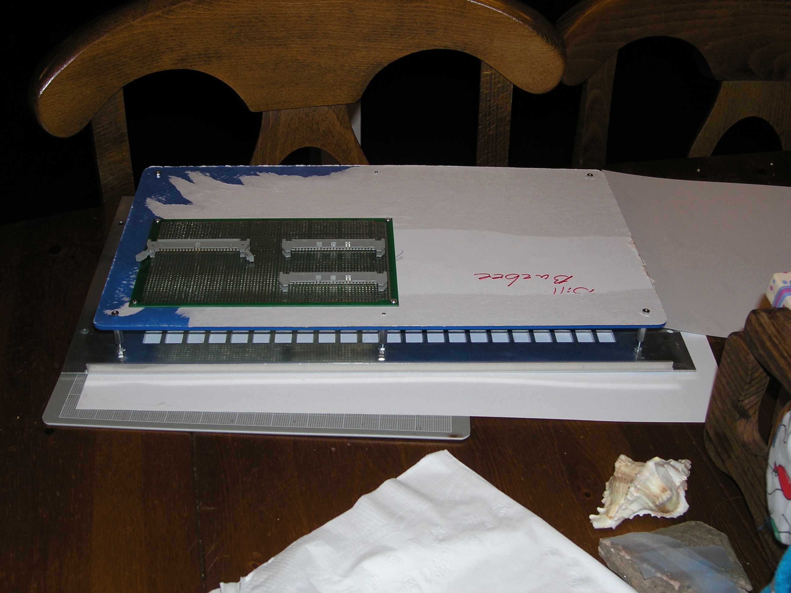
The top edge of the card will be mounted flush against the inside of the lower back panel using the brackets shown. To cut the slot in the back panel, I plan to drill a pilot hole and then use a nibbler. Sharp edges will be smoothed with a file or my handy-dandy Dremel tool. The Kittyhawk drive appears in the picture, but is hard to see. It is mounted immediately to the right of the compact flash card standing up on end. To save on space, I'm using a DIP switch for the clock and RAM/ROM switches. The larger card at the bottom is the front panel socket card. The ribbon cables from M1's card cage will snake under the cage and attach to this card. The sockets are wire-wrap, and will be wired to the LEDs and switches on the front panel. Also on this card will be a small amount of logic to support the POST code display. Also, I've taken Magic-1 offline. To avoid excessive mechanical strain, I think I'll keep it offline until I get these two cards in place. 4/16/2005Did all of the rewiring work - about 60 or so wires. Haven't done extensive testing yet. I think I'll wait for the new front panel. The reason is that I'm trying to minimize the number of times I remove cards from the cage. Next up is building the board to hold the sockets for the front panel. On the artwork front, I made a few changes. Here's the latest:
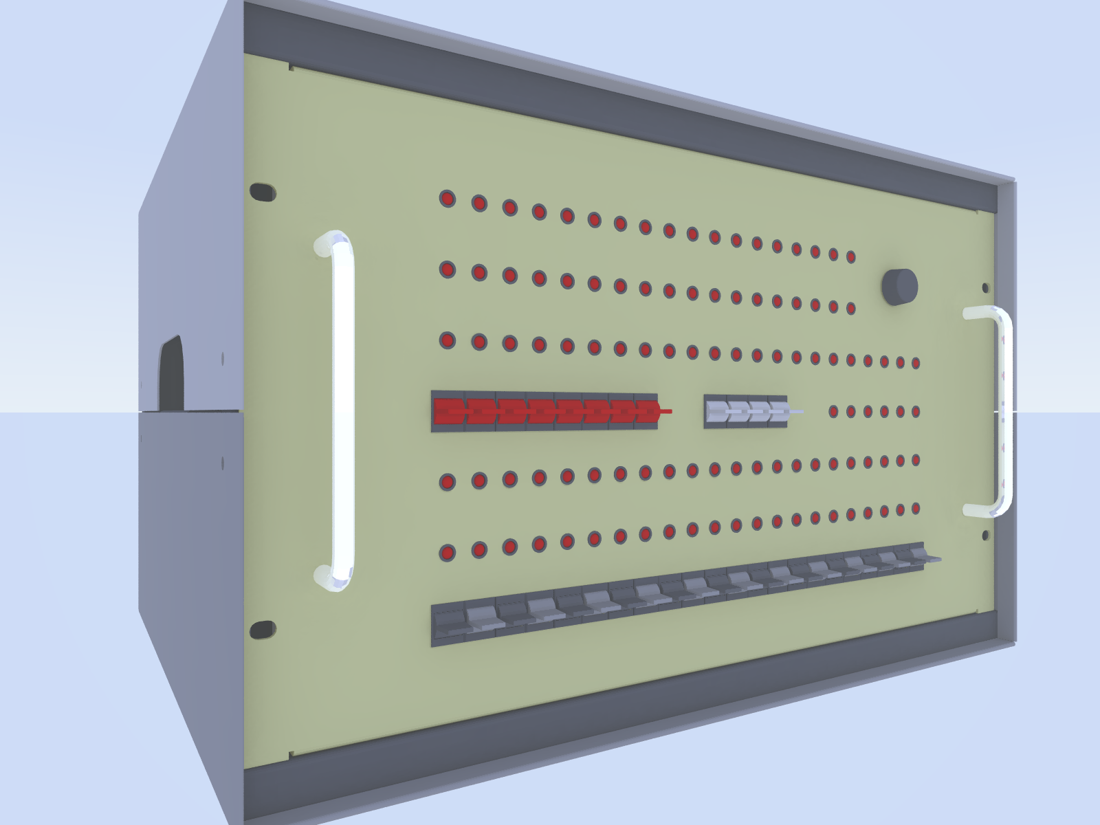
The main change is moving the single-step clock toggle from the back panel to the front. It will swap positions with the switch that selects between ROM for the first 16K bytes of physical memory and SRAM. Also, it turns out that I did not make a mistake in the register select switch artwork. When I tested it yesterday, and switch shifted positions a bit. All is well. Oh, I also decided to get rid of the black switches. All white from here on out. 4/15/2005Did a full switch mockup tonight:
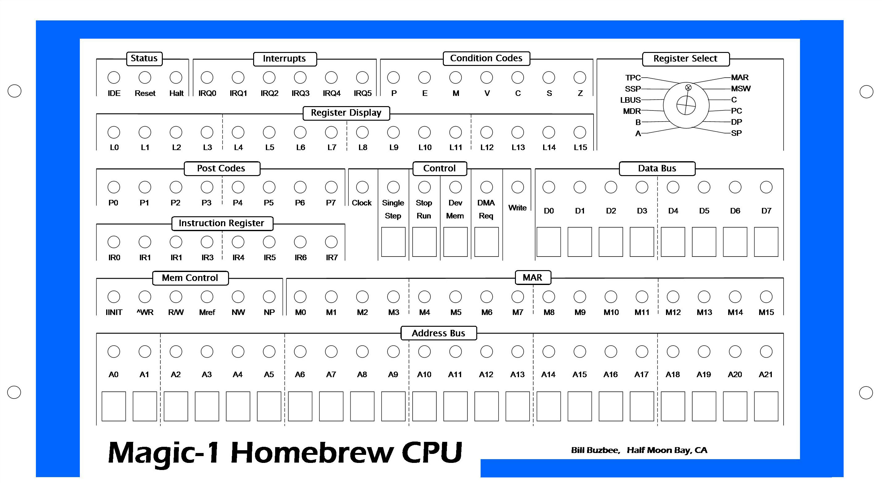
It's looking pretty good, but I'm still debating over a few minor items. First, I put in black switches to mark the MSB of each nibble. However, the black paddle just gets lost with the black bezel. Looks kind of like missing teeth. If I had red, blue or grey it might work. At the moment, I'm leaning towards just doing all white. On the rotary register display select switch, I discovered a labeling problem. The positions on the left side are rotated 15 degrees too far. Not sure how I did that. Finally, the red dot in the middle of the display is the push-button switch to write data into memory when toggling stuff in. The label is a bit too close - it gets lost under the button. I think it's okay to have the labels for LEDs close because they are almost flush with the panel. However, I think I'll drop the WR label to the same level as the D0..D7 switch labels. Also tonight, I installed a new power supply. The old one was very, very noisy. The new one has temperature-controlled fans, and is almost totally silent given the relatively low power draw. The only distasteful thing I had to do was add a power resister across the 12V supply in order to force the minimum load (800 ma) needed for regulation. I'm using a nice aluminum 25 watt one bolted to the case for heat dissipation. It's going to be a busy weekend on the home front (daughter Maia, age 7, has two performances with the dance class, plus swimming lessons and a friend's birthday party). If I find the time, I'll do all of the rewiring to move the switch pull-ups to the device card and the register select rotary switch inverter to the front panel logic card. 4/14/2005I think I'm about done with the artwork for the front panel. Here's what it looks like now:
This weekend I'll mostly be working on rewiring to go with the new switch design, but I will do a more elaborate mockup using a throwaway copy of the front panel art. I want to see what it looks like with switches and a few LEDs. Mostly, I'll play with the register select knob and try using different color paddle switches for the most significant bit of each nibble. Then, assuming all goes well, I'll do a final print and get it laminated sometime next week. (Hmm, now that I'm looking at it again, I think I need a little more space on the left-hand side of the register select box. It's a bit crowded against the end of the condition code and register LEDs). One other thought I had was that it might be nice to have the name "Magic-1" be in some sort of stylized font - perhaps with a magic wand for the "i" and a shooting star for the dot on the I. Or maybe not. 4/13/2005Spent this evening's session updating the schematics (now uploaded). When looking over the switches, I realized that I'd designed them pretty poorly. This isn't surprising - it was among the first things I did. Anyway, rather than switching between power and ground, it's much easier to just use a pull-up resistor on the switch output and then switch to ground. I had actually wired things this way on the temporary front panel, but I decided it would be cleaner if the pull-ups were moved to the device card. Also, I have decided to go ahead and use 12 register position for the register display switch. For the time being, I'll just drop the ability to display the fault register. If I ever need to debug that, there are other mechanism (and I could also just pull out the old temporary front panel - which would probably be easier to use anyway with its hex digits). I'll have an evening or two worth of wiring work on to update the switch scheme, as well as the inverted register switch. I want to make these changes and get them working with the temporary front panel first. Once that's done, I'll start working on the board that will hold the sockets for the new front panel. There are only a few signals it needs to supply to be able to remove the temporary front panel. Oh, I also decided to give the front panel LEDs a separate power feed controlled by a switch on the back of the machine. Magic-1 will likely stay in the master bedroom for a while, and with all of the LEDs going it would probably generate too much light to sleep. There is already a cut-out for a switch on the back (it was intended to be used as an on/off switch, but my power supply has that already built in). I'll use that to turn off the bulk of the front panel LEDs at night. 4/12/2005Hit a couple of minor snags on the register select dial. First, I miscounted. There are 13 possible registers that can be displayed, not 12 - which makes my idea of using every other position in my 24-position rotary switch a bit more difficult. Secondly, the way I have the switch wired it uses negative logic for the encoded position. This wasn't a problem when I used all 24 position, but is an issue with 12. However, I think I like the idea of using every other position. It will make the panel much easier to read and use. At minimum, I'll have to add an inverter for the signal lines coming off the switch. Not a big deal. The big question is whether I should just eliminate one of the possible register displays. The one that might go is the one that holds the most recent fault code. It actually wouldn't be a big deal to lose. Alternately, with a bit of decoding glue logic I could go ahead and make it work by having one of the "in-between" switch position select it. 4/11/2005Making good progress on the artwork for the front panel. I've got a bit of aligning to do, but overall I like the general scheme. The plan of using a shovel-blade Exacto knife and a 7mm hole punch seem to be working out well. Some minor changes to go: I think I'm going to move the reset button to the back of the enclosure, recessed. In its place, I'll put in a LED for IDE drive activity (forgot that one earlier). The switch that I have to select which register to display is a 24-position encoded rotary switch (very nice surplus find). However, I only have 12 positions for it. At the moment, I've put them all to one side. One possibility is to ignore the least significant bit and make every other stop significant. That would make the layout of the register labels a bit more consistent. Also, I have to track down a copy shop that can do a thin laminate of the print side of the artwork. If all goes well, I might be able to start wiring this weekend. Anyway, here's the current version with a few switches installed:
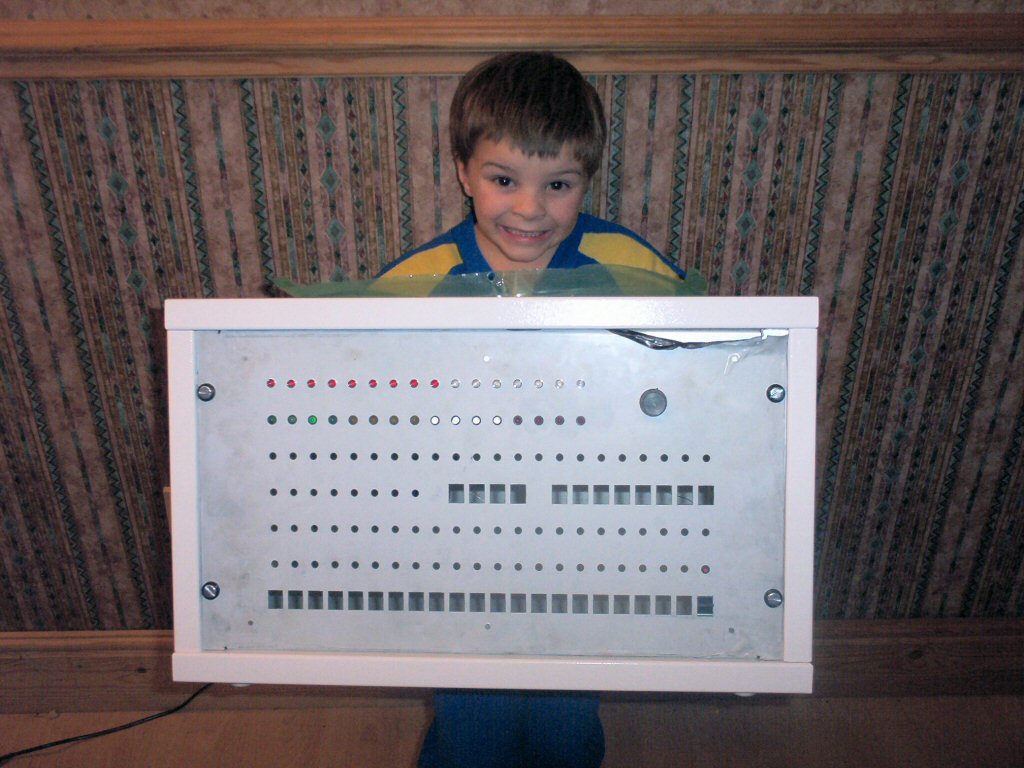
4/9/2005I arrived home from a week-long vacation last week to find an incredible surprise on my doorstep - Alistair Roe built and sent me a spectacular custom enclosure and front panel for Magic-1. We'll have more detail on it's construction later, but here's a photo with Alistair's son Callum modeling:
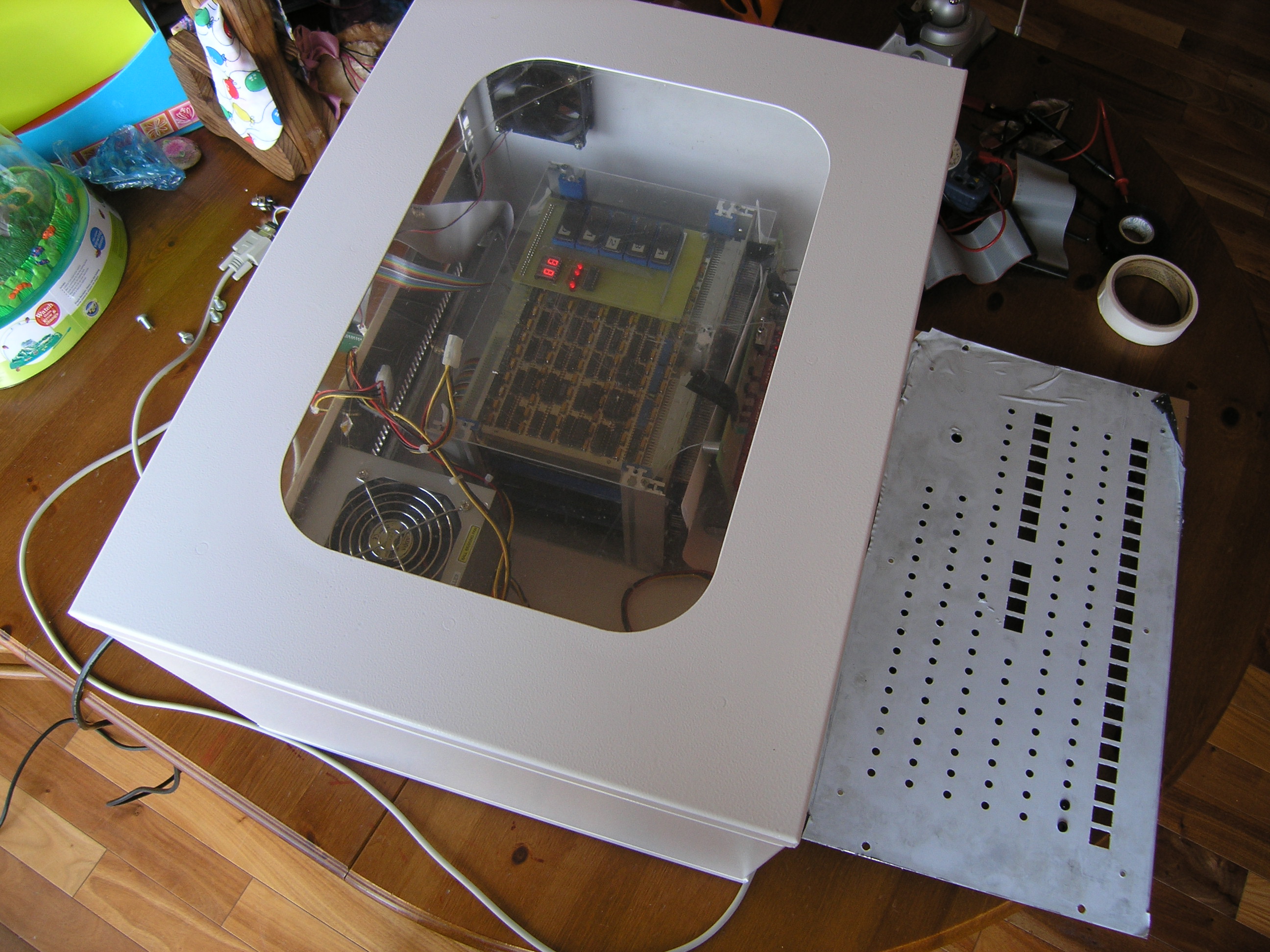
The enclosure was constructed from 1.5 mm aluminum, weld free construction and held together by M5 screws and nuts. The panels are 2mm aluminum with 10mm folds for added rigidity. Today, I started moving Magic-1 into its new home. Here are the two side-by-side. Note the cut-out on the top. It's covered by some protective film in this shot, but it will allow a view inside of the enclosure. I've begun experimenting with front panel labels and lettering, and have a partial mock-up showing here.
The first step is to just place M-1 in the enclosure. However, to do this I needed to create a new set of ribbon cables to go to the real front panel. The ones I have go to the temporary front panel on the card-opening side of the card cage. For the real front panel, the cables will need to wrap around the cage on the bottom (as the front panel will be on the other side. I built the cables using rainbow ribbon and a vise to attach the IDC connectors:
In this next picture, you can see the new ribbons snaking under the cage. The view is from the front:
Here's a top view through the window. I've removed the top layer of protective file, but not the bottom, so it's a little dark:
Finally, here's a rear shot. For now, I'm just dangling the IDE drives out the back. I'll probably mount those on the rear of the top panel (though I might try to get tricky and cut a slot in the lower panel so the compact flash card can be swapped without removing the panel.
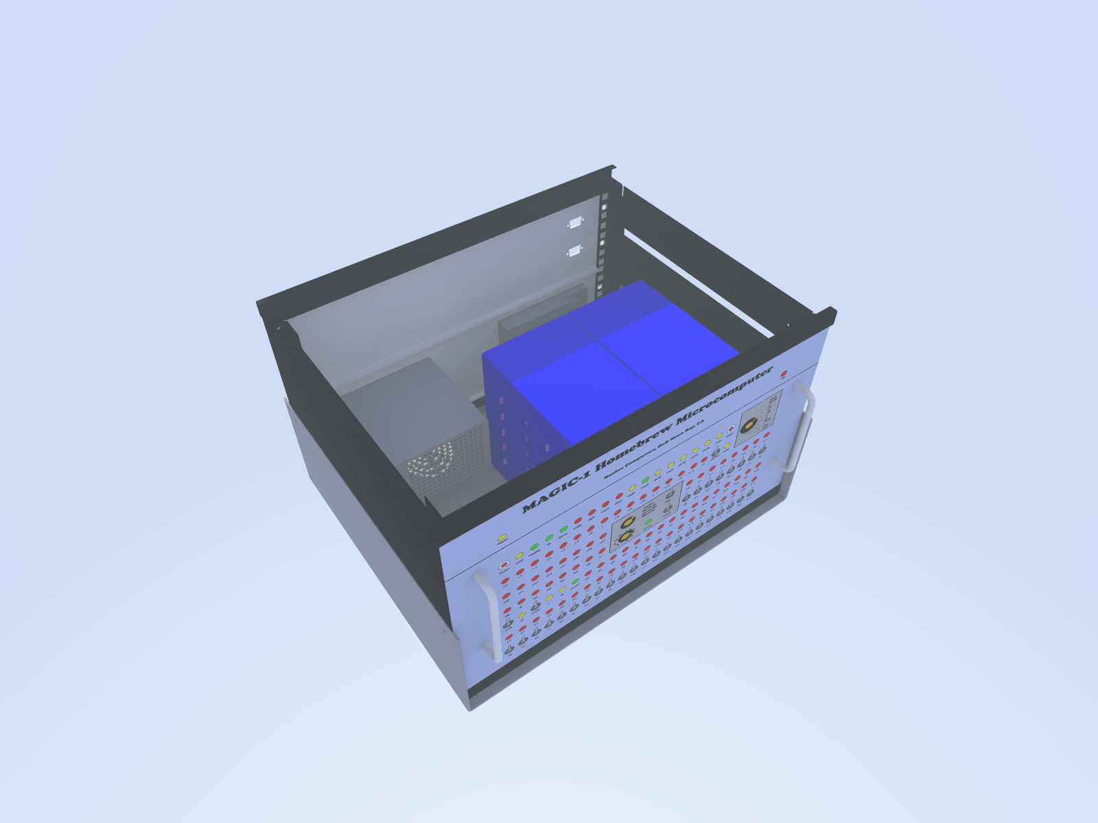
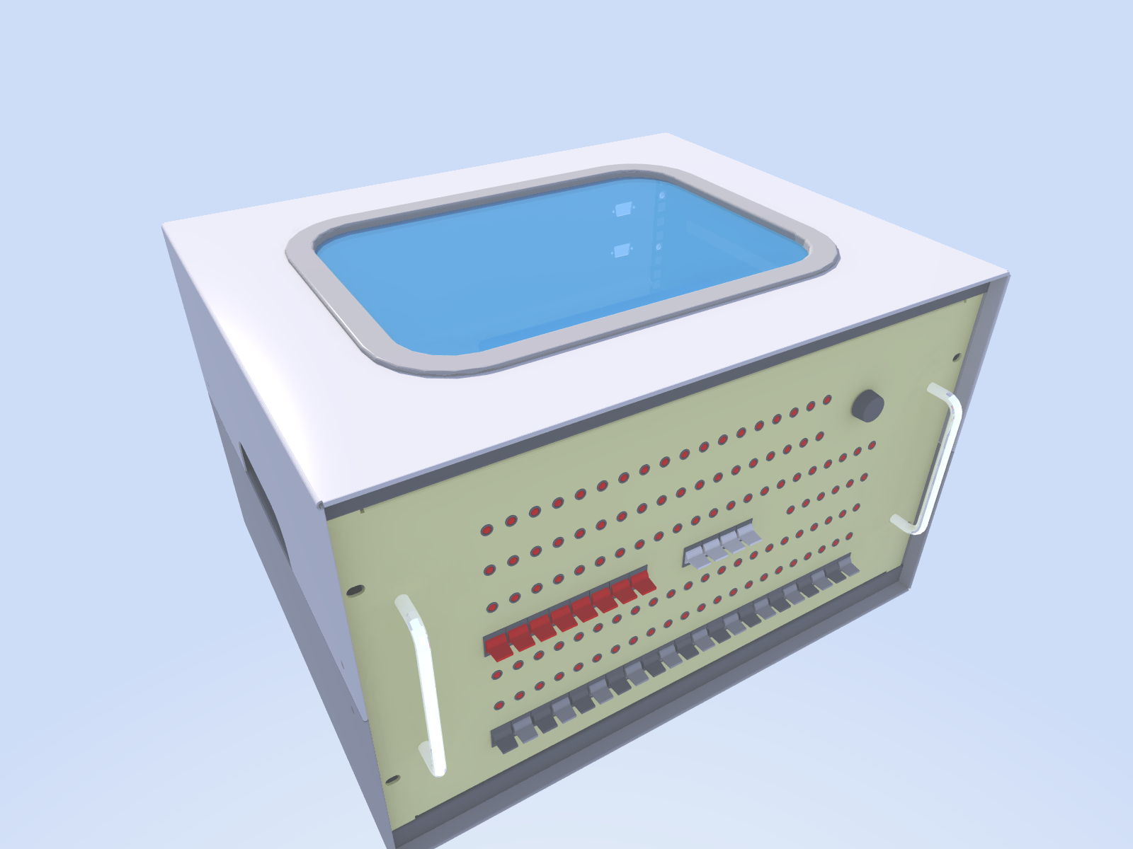
Next up is finishing the lettering for the front panel. My plan is to print out a full cover for the front panel using my large-format (Super B) inkjet printer on photo paper. I'll then take it to a local copy shop and get the print side laminated. To cut the rectangular holes, I'll use a square Exacto blade, tapping it with a hammer like a chisel. For the LED holes, I located a 7mm circle punch that should work. Other minor details include raising the card cage an inch or so to enable the bottom card to be removed (mounted to the bottom now, it would conflict with the bottom lip of the enclosure). I also think I'm going to shop around for a PC power supply that is quieter. I'm not using that much power, so if I can find one that only turns on its fans when necessary, things should work better. 5/16/2004Now that Magic-1 is acting like a real computer, it's time to make it look like one. I've toyed with a lot of plans, including an acrylic cube, black tower, and other even sillier notions. But, it pretty much all comes back to a good old 19" box with lots of switches and LEDs. Alistair Roe has been instrumental in refining the enclosure concept, and has even gone so far as to come up with some ray-traced 3-D models. The general idea is a 6U instrument case with the card cage bolted inside. The LEDs would be mounted directly to the front panel through holes. For switches, I'm leaning towards paddles. Here's Alistair's concept:
Although I've got plans for three rotary switches (clock select, slow clock speed and register select), Alistair suggests that we move the clock controls to the back - otherwise the front is getting a bit cramped. A good idea, I think. Here's a model he did with the front panel mockup I put together a year or so ago:
It is a bit cramped with the extra switches. Note also the top window. This is a particularly nice touch. This could allow for viewing of the POST code display. The next step is to find a good 6U instrument case. I'll be scanning eBay and scavenging the surplus shops. Meanwhile, here are some more concept pictures: Showing the card cage and power supply:
Rotated full model:
And finally, the obligatory ray-trace scene (minus the chrome spheres...):
|